background image

UL_–53      

© 

Dinel, s.r.o.

10

• 

The measuring device 

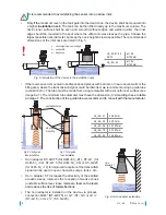
shall not be installed

 in places 

with direct sunlight and shall be protected against weather 

conditions. 

Direct sunlight affects the built-in temperature 

compensation! 

• 

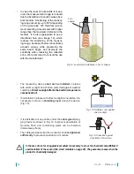
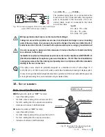
If installation in places with direct sunlight is inevitable, it is 

necessary to mount a 

shielding cover

 above the device 

(Fig. 15).

• 

It is advisable to keep cable under the 

cable gland 

(sag-

ging down) as shown in Fig. 16 to prevent penetration of 

moisture. Rain and condensing water can be therefore 

drained away freely.

• 

The cable gland as well as the connector shall be 

tightened 

sufficiently

 to prevent penetration of moisture.

Fig. 15: Shielding cover against 

direct sunlight

Fig. 16: Protection against 

penetration of moisture

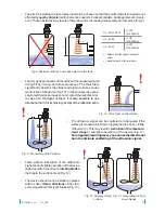
Fig. 14: Level meter installation in silo or hopper

horn

adapter

• 

In case the level of bulk solids is meas-

ured, the measurement range is reduced 

due to absorption of acoustic waves by a 

bulk medium. Shortening of the measur-

ing range occurs by up to 50% depending 

on the grain size. We therefore recom-

mend selecting a level meter with higher 

range than the maximum distance to the 

medium. It is also appropriate to use a 

directional horn (see image 14), which 

reduces the shortening of the measur-

ing range, because it better concentrates 

acoustic energy while preserving the 

same beam angle, and improves the 

sensitivity  when  receiving  the  reflected 

echo. We recommend to consult the use 

with the manufacturer.

In the case of use for an aggressive medium is necessary to prove the chemical compatibility of  

used materials of the sensor (Tab. Used materials on page 26). The guarantee ceases when the 

product is chemically damaged.

Summary of Contents for ULM-53 series

Page 1: ...ully the instructions provided in this User s Guide and keep it for future use The manufacturer reserves the right to make changes without previous notice INSTRUCTION MANUAL průmyslová elektronika Ultrasonic Level Meters ULM 53 Ultrasonic Level Sensors ULS 53 ...

Page 2: ......

Page 3: ...ions 7 9 Electrical connection 11 10 Set up elements 14 11 Status indication 15 12 Setting 16 12 1 Setting procedure for level meters ULM 53 17 12 2 Setting procedure for level sensors ULS 53 19 13 Protocol Modbus 21 14 Order code 21 15 Accessories 22 16 Safety protection compatibility and explosion proof design 22 17 Use operation and maintenance 23 18 General conditions and warranty 23 19 Markin...

Page 4: ...articularly important characteristics of the equipment 2 Packaging transport and storage The ULM 53 or ULS 53 device is packed in a cardboard packaging and the whole shipment is placed in a cardboard box The cardboard box is suitably filled to prevent mechanical damage dur ing transport Remove the device from the package just prior to its use to prevent possible damage Transport to the customer is...

Page 5: ...ices are suitable for continuous or limit meas urement of the level of liquids waste water sludge suspensions adhesives resins in various open and closed vessels sumps open channels and drains Applicability for measuring the surface level of loose materials is limited the range of measurement is shorter there Setting is carried out either using two buttons or a magnetic pen or by remote setting in...

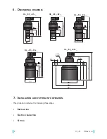
Page 6: ...al drawings ground terminal UL_ 53_ 02 _ UL_ 53_ 06 _ UL_ 53_ 10 _ UL_ 53_ 20 _ Al alloy This procedure includes the following three steps Installation Electric connection Setting 7 Installation and putting into operation UL_ 53_ 01 _ ...

Page 7: ...2 In compliance with the measuring principle no signals reflected in the area directly below the device dead zone can be evalu ated The dead zone Fig 2 determines the minimum distance possible between the device and the highest level The minimum distances to the medium are listed in the chapter Technical specifications The device shall be installed so that the surface does not interfere with the d...

Page 8: ...LM 53_ 06 or ST G2 25 forULM 53_ 10 forimprovedreceptionofthetransmitted signal can be used in open channels sumps tanks etc Horn adapter ST increases the directivity of the emitted acoustic waves improves the reception of weak echoes unstable surface level loose materials foam on the level and reduces the risk of falsereflections The horn adapter is installed on the device via process connection ...

Page 9: ...eter UL_ 53 01 02 10 x c 12 min 200mm UL_ 53 06 x c 8 min 200mm UL_ 53 20 x c 10 min 200mm Fig 9 Minimum distance from close objects in the tank Foammaybeproducedonthesurfaceofthemeasuredliquid during filling mixing and other processes The thick foam significantly absorbs the ultrasound signal and may cause malfunction of the device Fig 10 In those cases it is neces sarytotestthedeviceinadvanceorc...

Page 10: ...ure Fig 14 Level meter installation in silo or hopper horn adapter In case the level of bulk solids is meas ured the measurement range is reduced due to absorption of acoustic waves by a bulk medium Shortening of the measur ing range occurs by up to 50 depending on the grain size We therefore recom mend selecting a level meter with higher range than the maximum distance to the medium It is also ap...

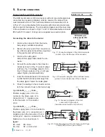
Page 11: ...connector back to the device body Fig 17 Connection diagram of the ULM level meter variant I and inside view of the connector Fig 18 Connection diagram of the ULM level meter variant U and inside view of the connector BN 1 BU 2 mA U 0V V U 0V U Uout V U 0V U Uout mA U 0V U 0V BN 1 BU 2 BK 3 U 0V BN 1 BU 3 BK 4 BN 1 BU 3 BN 1 BU 2 BK 3 BN 1 BU 3 BK 4 BN 1 BU 2 mA U 0V mA U 0V BN 1 BU 3 BN 1 BU 2 mA...

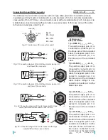
Page 12: ...the connector BN 1 BU 2 mA U 0V V U 0V U Uout V U 0V U Uout mA U 0V U 0V BN 1 BU 2 BK 3 U 0V BN 1 BU 3 BK 4 BN 1 BU 3 BN 1 BU 2 BK 3 BN 1 BU 3 BK 4 BN 1 BU 2 mA U 0V mA U 0V BN 1 BU 3 BN 1 BU 2 mA U 0V V U 0V U Uout V U 0V U Uout mA U 0V U 0V BN 1 BU 2 BK 3 U 0V BN 1 BU 3 BK 4 BN 1 BU 3 BN 1 BU 2 BK 3 BN 1 BU 3 BK 4 BN 1 BU 2 mA U 0V mA U 0V BN 1 BU 3 Valid for UL_ 53_ _ _ _ _ C _ Performance C wi...

Page 13: ...M level meter with a voltage output variant U Valid for UL_ 53_ _ _ _ _ B H _ Performance B with short cable gland Performance H with cable gland for protective hose Type ULS 53_ _ _ _ S B H _ The positive supply pole U is connected to the brown wire of the connected cable the negative pole is connected to the blue wire of the con nected cable Type ULM 53_ _ _ _ M B H _ Level meters are designed f...

Page 14: ... nected cable Load is connected to the black wire of the cable It is also necessary to design and take measures to reduce the effects of static electricity to a safe level in the wiring InstallationinexplosiveatmospheresneedstobecarriedoutincompliancewithEN60079 14 Electricalinstallationsforexplosivegaseousatmospheres Part14 Electricalinstallations indangerousareasotherthanmining andpossiblyalsoin...

Page 15: ...ltrasound transducer is dirty This fault signal is triggered after 5 measurements in dead zone After one measuring outside out the dead zone the fault signal cancels LED stops flashing rapidly and the current voltage is set to the current level off the level meter is not capable of receiving the echo Incorrect installation or malfunction This fault signal runs after 20 lost echoes After one correc...

Page 16: ...indicated by the STATE indicator lamp The L version level meter does not have any setting controls and indication LEDs Pre defined ranges are factory set applicable to current and voltage outputs The level meter variant with a Modbus type output is set by means of two way communication via the RS 485 industrial bus with the Modbus RTU protocol A list of applicable registers is given in a separate ...

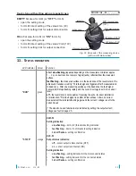
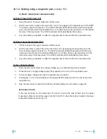
Page 17: ... at least additional 3 s to set the value to 20 mA 10V directly In that case you can skip step 3 3 Press the DOWN and UP buttons to accurately set any value in individual increments hold the relevant button to increase the adjustment step gradually 4 Press both buttons simultaneously for at least 1 s to confirm the set values The STATE indicator LED briefly flashes three times 5 Any other setting ...

Page 18: ...pen on the flat area for at least additional 3 s to confirm the set value and store it in the internal memory of the level meter The STATE indicator LED briefly flashes three times 3 Any other setting is possible 2 s after the magnetic pen is removed from the sensitive area Factory default settings 1 Disconnect the level meter from supply voltage e g by disconnecting the connector 2 While there is...

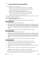
Page 19: ...ttings 1 Disconnect the sensor from supply voltage e g by disconnecting the connector 2 Press the OFF and ON buttons at the same time while supply voltage is disconnected 3 Connect supply voltage while keeping the OFF and ON buttons pressed 4 Wait approx 4 s for 3 short flashes of the orange STATE indicator LED After that release both buttons 5 Now the level meter is restored into factory default ...

Page 20: ...by placing the magnetic pen to the ON sensitive area for at least 2 s The STATE indicator LED flashes quickly Hold the magnetic pen on the ON flat area for at least additional 3 s to confirm the set value and store it in the internal memory of the level meter The STATE indicator LED briefly flashes three times 3 Any other setting is possible 2 s after the magnetic pen is removed from the sensitive...

Page 21: ...S limit switch Set up elements T buttons M smagnetic pen MP8 L no setting no LED cable cable length in m only for variants with connection type B and H adjustable range in dm only variants without setting controls L with output type I and U Data communication takes place along a series line of a standard RS 485 with protocol Modbus RTU A list of relevant variables is provided in a separate annex T...

Page 22: ...997 Coll as amended The supplied electrical device conforms to the applicable government regula tions concerning safety and electromagnetic compatibility optional for a extra charge stainless steel or plastic fastening nuts G G1 G1 and G2 stainless steel or plastic lugs G G1 G1 and G2 horn adapter ST G0 75 ST G1 thread G1 ST G1 5 and ST G2 25 socket ELWIKA 4012 K PG7 standard included in device pr...

Page 23: ... level meter and the ULS 53 sensor do not require any maintenance for operation During operation the operators of the technology are informed of the level height of the measured material through a connected display unit Maintenance of the device consists in verification of integrity of the device and the supply cable Depending on the nature of the material measured we recommend to verify the clean...

Page 24: ...ity system 1026 applies to version ULM 53Xi electric waste take back system mark Sample label for device type ULM 53Xi 02 G I C T Labels for device type ULS 53_ _ _ _ _ _ _ manufacturer s symbol Dinel logo Internet address www dinel cz country of origin Made in Czech Republic connection diagram and marking of wires U 0V for version ULS 53N Ui 0V for version ULS 53Xi level meter type ULS 53_ _ _ _ ...

Page 25: ...rature range UL_ 53_ 01 _ 02 _ 06 _ UL_ 53 10 _ 20 _ 30 70 C 30 60 C Short time temperature stress resistance 90 C 1 hour Measuring period UL_ 53_ 01 _ 02 _ UL_ 53_ 06 _ 10 _ UL_ 53_ 20 _ UL_ 53_ __ M 0 5 s 1 2 s 5 0 s adjustable through Modbus RTU Averaging UL_ 53_ __ _ ULM 53_ __ M 4 measurements 3 adjustable through Modbus RTU Maximum operating overpressure on transmission surface 0 1 MPa Limit...

Page 26: ...m 0 20m 0 20m 0 4m 0 5m Maximum range 4mA 1m 2m 6m 10m 20m ULS 53_ 01 ULS 53_ 02 ULS 53_ 06 ULS 53_ 10 ULS 53_ 20 Connection level ON 0 45m 0 90m 2 7m 4 5m 9m Disconnection level OFF 0 65m 1 30m 3 9m 6 5m 13m Technical data level meter Recommended cable ULM 53_ __ I ULS 53_ __ S ULM 53N __ U ULS 53N __ P ULM 53N __ M PVC 2 x 0 75 mm2 PVC 3 x 0 50 mm2 PVC 2x2 0 25 mm2 Maximum load resistance of cur...

Page 27: ...27 Dinel s r o UL_ 53 ...

Page 28: ...U Tescomy 249 760 01 Zlín Czech Republic Phone 420 577 002 002 Fax 420 577 002 007 Email sale dinel cz www dinel cz You can find the current version of the User s Guide at www dinel cz industrial electronics 1 2017 ...

Reviews: