11
©
Dinel, s.r.o. UL_–53
Connection through ISO connector
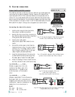
The ULM level meter or ULS level sensor with a G type cable gland are
connected to processing (display) units by means of a cable with an
outer diameter of 6 to 8 mm (recommended wire cross-section 0.5 to
0.75 mm
2
), via a detachable ISO connector with inner screw terminals,
which is part of the delivery. The connection diagram and the inner view
of the connector are shown in Fig.17 and 18. Non-detachable connector
IP67 with PVC cable 5 m long can be supplied as an extra option.
legend:
BK – black
BN – brown
BU – blue
NC – not connected
0 V
Uout
+U
0 V
+U
9 . E
lEctric
connEction
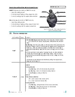
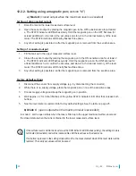
Connecting the cable to the device:
1. Unscrew the connector from the device
body using a suitable screwdriver.
2. Remove the inner part of the connector us-
ing a flat screwdriver (insert the screwdriver
in the gap marked with an arrow).
3. Unscrew the cable gland
and pull the supply cable inside the con-
nector.
4. Connect the cable wires to the screw ter-
minals as shown in Fig. 17 (current output
4-20 mA), Fig. 18 (voltage output 0-10 V),
Fig. 19 (S type output) or Fig. 20 (P) type
output. Tighten the terminals firmly.
5. Insert the terminals back in the connector
so that the NC terminal points away from
the cable gland. Fasten the cable gland.
6. Check the sealing on the connector and at-
tach the connector back to the device body.
Fig. 17: Connection diagram of the ULM level meter
(variant –I) and inside view of the connector
Fig. 18: Connection diagram of the ULM level meter
(variant –U) and inside view of the connector
BN ( )
1
BU ( )
2
mA
+U
0V
V
+U
0V
U
Uout
V
+U
0V
U
Uout
mA
+U
0V
+U
0V
BN (1)
BU (2)
BK (3)
+U
0V
BN (1)
BU (3)
BK (4)
BN ( )
1
BU (3)
BN ( )
1
BU ( )
2
BK (3)
BN ( )
1
BU (3)
BK (4)
BN ( )
1
BU ( )
2
mA
+U
0V
mA
+U
0V
BN ( )
1
BU (3)
BN ( )
1
BU ( )
2
mA
+U
0V
V
+U
0V
U
Uout
V
+U
0V
U
Uout
mA
+U
0V
+U
0V
BN (1)
BU (2)
BK (3)
+U
0V
BN (1)
BU (3)
BK (4)
BN ( )
1
BU (3)
BN ( )
1
BU ( )
2
BK (3)
BN ( )
1
BU (3)
BK (4)
BN ( )
1
BU ( )
2
mA
+U
0V
mA
+U
0V
BN ( )
1
BU (3)
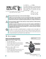
Valid for: UL_-53_-_ _-_-_-G-_
Performance„G“
with connector ISO
Type
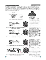
ULS–53_–_ _–_–S–G–_
Positive supply pole +U is con-
nected to the brown wire or to
connector pin 1, negative pole
to the blue wire or to connector
pin 2.
Type
ULS–53_–_ _–_–P–G–_
Positive supply pole +U is connected to
the brown wire or to connector pin 1,
negative pole to the blue wire or to con-
nector pin 2. Load is connected to the
black wire or to connector pin 3.
+U
0 V
Uout
+U
0 V
Fig. 19: Connection diagram of the ULS
sensor with S type output
(two-state current switch 4 mA / 20 mA)
Fig. 20: Connection diagram of the ULS sensor with P type
output (PNP) with an open collector
BN ( )
1
BU ( )
2
mA
+U
0V
V
+U
0V
U
Uout
V
+U
0V
U
Uout
mA
+U
0V
+U
0V
BN (1)
BU (2)
BK (3)
+U
0V
BN (1)
BU (3)
BK (4)
BN ( )
1
BU (3)
BN ( )
1
BU ( )
2
BK (3)
BN ( )
1
BU (3)
BK (4)
BN ( )
1
BU ( )
2
mA
+U
0V
mA
+U
0V
BN ( )
1
BU (3)
BN ( )
1
BU ( )
2
mA
+U
0V
V
+U
0V
U
Uout
V
+U
0V
U
Uout
mA
+U
0V
+U
0V
BN (1)
BU (2)
BK (3)
+U
0V
BN (1)
BU (3)
BK (4)
BN ( )
1
BU (3)
BN ( )
1
BU ( )
2
BK (3)
BN ( )
1
BU (3)
BK (4)
BN ( )
1
BU ( )
2
mA
+U
0V
mA
+U
0V
BN ( )
1
BU (3)
Summary of Contents for ULM-53 series
Page 2: ......
Page 27: ...27 Dinel s r o UL_ 53 ...


