background image

db CodeLock 

                                                                Version 1.3 

                                          Digitus Biometrics, Inc. 2017 


Page 7 of 10 


Connect the cable to the Remote Node / db Sentry Controller – Step 4 


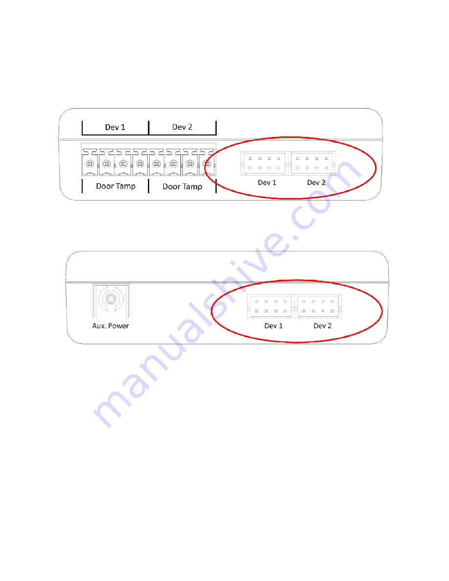
Locks are connected to the Remote Node or db Sentry’s socket circled in the diagram below. 


Each Remote Node / db Sentry Controller has two device inputs, Dev 1 and Dev 2. 


Side View of Remote Node 


Side View of db Sentry 


It is recommended that for a cabinet with 2 doors, the front door is connected to Dev 1 and the back door is connected to 

Dev 2. 

Summary of Contents for CodeLock

Page 1: ...db CodeLock Installation Manual Version 1 0 ...

Page 2: ...oor Lock Step 1 4 Mount the tie down pads to the Door and Cabinet Step 2 5 Route the Cable between the lock and the Remote Node db Sentry Controller or ACM Panel Step 3 6 Connect the cable to the Remote Node db Sentry Controller Step 4 7 Connect the lock to 3rd party Access Panel 8 Connect the SENSE OUT to monitor the lock position open closed 9 ...

Page 3: ...8175 Figure 1 Standard Pawl Pawl with Rod Control H mm Model H mm Model 4 1000 112 4 1000 U63 6 1000 22 6 1000 U21 8 1000 113 8 1000 U64 10 1000 21 10 1000 U22 13 1000 20 13 1000 U23 14 1000 19 14 1000 U24 16 1000 18 16 1000 U25 18 1000 17 18 1000 U26 20 1000 16 20 1000 U27 22 1000 15 22 1000 U28 24 1000 14 24 1000 U29 25 1000 27 25 1000 U30 26 1000 50 26 1000 U31 28 1000 13 28 1000 U32 30 1000 28...

Page 4: ...ottom mounting bracket as show in Figure 1 Do not over tighten the screws in the bottom mounting bracket as this may jam the lock mechanism Page 3 of this document describes how to determine which pawl you will need depending on the make and model of cabinet Pay particular attention to the rotation limiter This is installed as shown depending on whether you have a right on left hand opening door P...

Page 5: ...secure the supplied cable that connects the lock directly to the Remote Node db Sentry or ACM panel Ensure that the door surface is clean and free from any debris Using neat alcohol to clean the surface is highly recommended Allow drying time before proceeding Figure 2 Remove the protective cover from each tie down pad and situate as shown in Figure 2 ...

Page 6: ... lock cable to the door hinge as shown in Figure 3 Secure the cable to the tie down pads using the supplied cable ties Connect the supplied device cable to the RJ 45 coupler and route it to the Remote Node or Sentry if using Digitus a controller If connecting to a third party access control panel connect a network cable to RJ 45 coupler and run back to panel Figure 3 ...

Page 7: ...s are connected to the Remote Node or db Sentry s socket circled in the diagram below Each Remote Node db Sentry Controller has two device inputs Dev 1 and Dev 2 Side View of Remote Node Side View of db Sentry It is recommended that for a cabinet with 2 doors the front door is connected to Dev 1 and the back door is connected to Dev 2 ...

Page 8: ...ine to unlock the handle Green White RED LED Connect to the Red LED output on the 3rd party panel Blue V Requires a 12VDC Supply Blue White LATCH POS used to indicate if the lock is open or closed Will be pulled to Ground GND if the handle is closed Will be open circuit if the handle is open See diagram below Green GREEN LED Connect to the Green LED output on the 3rd party panel Brown White Wiegan...

Page 9: ...tion open closed If the 3rd party Access Panel requires a 2 wire input to monitor the door positions an external relay is required Connect as follows Black Wire 3rd party Access Panel C NO NC V 0V External Relay V 0V SENSE OUT Connect to Blue White Wire from Lock DOOR SWITCH INPUT Yellow Wire Blue Wire Red Wire ...

Page 10: ...cs Inc 2017 Page 10 of 10 Digitus Biometrics Inc 2 East Bryan Street Suite 502 Savannah GA 31401 USA Phone 912 231 8175 Fax 912 629 9478 www digitus biometrics com support digitus biometrics com Specifications subject to change without notice ...

Reviews: