background image

DigitAx User Guide
Issue code: dgxu4

5-3

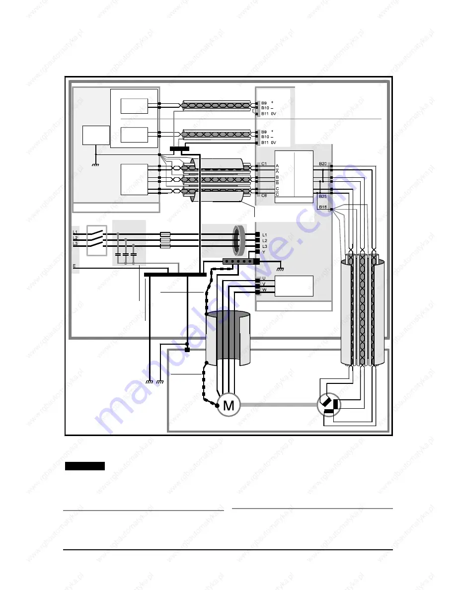
Note

Failure to follow the basic
recommendations shown in Figure 5–4 may
result in vibration in the motor or spurious
trips in the Drive.

Using the arrangement shown in Figure 5–4
does not guarantee that the specified
standards for conducted and radiated
emissions are met.   Additional precautions
and guidelines need to be considered.  
These are shown in Figures 5–5 and 5–6.

5.3 

EMC wiring recommendations

Power
supply

Analog speed reference

Simulated
Encoder
input

0V common

CNC controller

Control system ground bus-bar
4mm x 12mm x 100mm

Encoder
output

Resolver

input

Resolver

Motor

Enclosure

Drive

Ground cable connecting 
the bus-bars
Dia: 5mm to 10mm 
Max length: 0.9m (2ft 6in)

Safety-ground terminal

Ferrite 

absorber ring

Capacitor
network

Isolator

AC supply

Machine

System supply ground bus-bar
50mm x 20mm x 100mm min, 
200mm max 

Screened twisted-pair wires 

with overall screen 

Armoured or 
shielded cable

Screened twisted-pair wires 
with overall screen 

Output stage

Simulated encoder

This 
connection 
must be as 
short as 
possible

This 
connection 
must be as 
short as 
possible

The capacitor network and ferrite 

absorber ring are not required when 

an RFI filter is used.

Wiring arrangement for differential 
speed reference signal

Single-ended 
signal

Analog speed
reference input

Wiring arrangement for single-ended 
speed reference signal

Differential 
signal

Apply the signal to B9 as shown (or B10 for 
negative sense). Apply the 0V common 
connection to B10 (or B9). Also connect B11 to 
this 0V common connection at B10 as shown (or 
B9). Connect the cable shield to the control 
system bus-bar only. Do not connect B11 to the 
control system bus-bar.

Apply the signal to B9 and B10 as shown. 
Connect B11 to the control system bus-bar. 
Connect the cable shield to the control system 
bus-bar only.

0V

Figure 5–4 

Recommended connections, ground arrangements and other  minimum requirements
to ensure good noise immunity

Summary of Contents for DBE1100S

Page 1: ...NA Jana Dlugosza 2 6 Street 51 162 Wroc aw Poland biuro rgbelektronika pl 48 71 325 15 05 www rgbautomatyka pl www rgbelektronika pl DATASHEET www rgbautomatyka pl www rgbelektronika pl OTHER SYMBOLS...

Page 2: ...d with a wide variety of tools and having several testing stands at their disposal are a guarantee of the highest quality service OUR SERVICES ENCODERS SERVO DRIVERS LINEAR ENCODERS SERVO AMPLIFIERS C...

Page 3: ...User Guide DigitAx AC Servo Drive 1 4kW to 22kW Part Number 0415 0008 Issue Number 4...

Page 4: ...her DigitAx Drives there may be some differences between their software and the software in this product These differences may cause this product to function differently This may also apply to Drives...

Page 5: ...oke ratings 3 4 3 20 Dimensions 3 4 4 Mechanical Installation 4 1 4 1 EMC wiring recommendations 4 1 4 2 Planning the installation 4 2 4 3 Environment 4 4 4 4 RFI filters 4 4 4 5 Ferrite absorber ring...

Page 6: ...libration 10 5 10 9 Methods of speed control 10 6 10 10 Methods of torque control 10 7 10 11 Methods of position control 10 8 10 12 Quick reference 10 10 10 13 Programmable outputs 10 11 11 List of Pa...

Page 7: ...ded by enclosures IP code UL94 Flammability rating of plastic materials UL508C Standard for industrial control equipment Applies to models DBE1500 and DBE2200 only These products comply with the Low V...

Page 8: ...DigitAx User Guide Issue code dgxu4 iv...

Page 9: ...e power rating of the model Size 1 and size 2 cases have ingress protection to IP20 size 3 case to IP00 The model in the size 1 case is cooled by natural convection The models in sizes 2 and 3 cases a...

Page 10: ...art the Drive To display the operating status of the Drive An RS485 serial communications port allows the Drive to be controlled remotely using a host PC or plc Warning Enabling the Drive when zero sp...

Page 11: ...high integrity protection against hazards arising from a malfunction 2 4 Environmental limits Instructions in this User Guide regarding transport storage installation and use of Drives must be complie...

Page 12: ...of the Drive could lead to damage loss or injury a risk analysis must be carried out and where necessary further measures taken to reduce the risk This would normally be an appropriate form of indepen...

Page 13: ...ch is rated as IP00 in accordance with the IEC529 or NEMA 1 The cooling fans for the heatsink are rated at IP20 For Drives supplied in an IP00 case a DC bus choke inductor and an optional braking resi...

Page 14: ...r99 3200 RPM 12 bit when Pr99 3200 RPM 3 13 Response times Scanning rate for speed loop 512 s Scanning rate for current loop 128 s Sampling time of analogue inputs 512 s Rise time of digital outputs 1...

Page 15: ...inal supply voltage 3 18 Losses and efficiency Note Figures quoted are at maximum output power Model Total power loss Efficiency at 460V 4kHz 100 8kHz 100 4kHz 8kHz W W DBE140 105 93 0 DBE220 145 94 4...

Page 16: ...quoted are design minima Drive model Choke ratings Weight mH ARMS Apk kg lb DBE1500 1 50 45 85 6 4 14 DBE2200 0 70 75 143 8 4 19 3 20 Dimensions Refer to the following diagrams Heated air exhaust Moun...

Page 17: ...5 12 15 16 Depth of heatsink p 95 3 7 8 100 3 15 16 Width of heatsink g 62 2 7 16 109 4 5 16 Height of heatsink e 332 13 1 16 330 13 Mounting centres top bracket to bottom bracket a 359 4 14 1 8 359 4...

Page 18: ...xhaust Model size 3 DBE1500 DBE2200 Mounting plate for through panel mounting Mounting plate for surface mounting Model size 3 Mounting bracket detail Model size 4 Mounting bracket detail Figure 3 2 D...

Page 19: ...rall depth d 283 11 3 16 Depth of heatsink p 139 5 1 2 Height of heatsink e 466 18 5 16 Width of heatsink g 295 11 5 8 Total height of mounting plates b 522 20 9 16 Mounting centres top to bottom a 50...

Page 20: ...DigitAx User Guide Issue code dgxu4 3 8...

Page 21: ...s consult the supplier of the Drive Resolver wiring Simulated encoder wiring Signal connections from the resolver and from the simulated encoder input of the CNC controller must be connected to the Dr...

Page 22: ...dissipated inside the enclosure Through panel mounting gives the following Heat dissipated outside the enclosure Reduced ingress protection 2 Refer to Figure 4 1 to plan the layout of the equipment i...

Page 23: ...a separate RFI filter for each Drive AC supply cables These can enter the enclosure and be routed as required AC supply distribution and fuses or MCB Locate as required All AC power cables or bus bars...

Page 24: ...e Drive is to be installed directly beneath other equipment such as another Drive ensure the Drive does not cause the ambient temperature requirements of the equipment to be exceeded 8 Allow at least...

Page 25: ...a plug in unit which can be detached from the Drive for mounting in a panel Holes are required in the panel for the fixing studs and connector which project from the rear of the Control Keypad housing...

Page 26: ...A AA AA AA AA AA AA AA AA AA AA AA AA AA AA AA AA AA AA AA AA AA AA AA AA AA AA AA AA AA AA AA AA AA AA AA AA AA AA AA AA AA AA AA AA AA AA AA AA AA AA AA AA AA AA AA AA AA AA AA AA AA AA AA AA AA AA...

Page 27: ...part of the enclosure to encourage internal convection Otherwise increase the height of the enclosure or install stirrer fans 4 11 Heat dissipation in a ventilated enclosure If a high ingress factor i...

Page 28: ...DigitAx User Guide Issue code dgxu4 4 8...

Page 29: ...ertification for hazardous areas should be obtained for the complete installation of the motor and Drive 5 2 Access to the power connectors DBE140 DBE220 A main power connector and a braking resistor...

Page 30: ...us negative Out BR External braking resistor Out External braking resistor connections DC External braking resistor Out DC bus connection DBE1500 DBE2200 Power terminals are located along the top and...

Page 31: ...x Screened twisted pair wires with overall screen Armoured or shielded cable Screened twisted pair wires with overall screen Output stage Simulated encoder This connection must be as short as possible...

Page 32: ...ax length 90mm 3 in Extension bus bar Max length 60mm 2 in Bond the back plate to the power ground bus bar Alternative safety ground connection for the motor Optional external braking resistor Protect...

Page 33: ...h 10mm in Max length 90mm 3 in Extension bus bar Max length 60mm 2 in Alternative safety ground connection for the motor Optional motor isolator Armour or shields must be bonded using the isolator cas...

Page 34: ...t the cable entry point Refer to Radiated emissions in the EMC Data Sheet Bond the back plate to the power ground bus bar Bond the RFI filter to the back plate using the mounting screws See signal con...

Page 35: ...nections using a DIN rail connector Bond armour or shields to back plate using an uninsulated terminal Bond the DIN rail to the back plate Back plate Enclosure Bond the armour or shield to the back pl...

Page 36: ...ault would be indicated OC In this case output chokes may be required In difficult cases consult the supplier of the Drive The AC power should be applied through an isolator and a fuse or circuit brea...

Page 37: ...s decelerated in a short time the energy returned can be too great for the Drive to absorb The effect is to increase the voltage of the DC bus with the possibility of the Drive tripping due to overvol...

Page 38: ...isolator as shown in Figure 5 7 Do not connect the thermal overload protection relay so that it would disconnect the braking resistor since interrupting large direct currents will cause arcing Connect...

Page 39: ...BE420 DBE600 DBE750 DBE1100S External braking resistor connections Models Main power connector Braking resistor connector External braking resistor Thermal trip Thermal trip Braking resistor connector...

Page 40: ...this value of torque to be produced for up to 4 seconds 2 Refer to the the motor manufacturer s data to obtain the permissible overload for 4 seconds Then use this figure to calculate the intermitten...

Page 41: ...voltage more accurately The reduction in value does not increase the power dissipation since the average voltage across the resistor is reduced by the braking transistor operating as a chopper For thi...

Page 42: ...becoming short circuit as follows I V R A Rpk R 800 22 36 6 Calculate the overload factor for this condition as follows F I I S C Rpk SET 36 3 275 11 7 Use the tripping curves to find the time that th...

Page 43: ...l from resolver B21 B21 Cosine high In B22 B22 Sine low In Sine signal from resolver B23 B23 Sine high In B24 B24 Excitation low Out B25 B25 Excitation high Out Signal at 7 812 kHz for resolver 18 19...

Page 44: ...g input In When b6 0 these inputs are used as analog speed reference B10 B10 Analog non inverting input In When b6 1 these inputs are used as torque reference input Input Impedance 10k B11 B11 0V Cont...

Page 45: ...max Dutymax servomotors For other motors the resistor value should be selected so that the input signal at terminal B1 B1 is less than 5V at the motor trip temperature B2 B2 0V Control signal common B...

Page 46: ...Function Type Description C1 A Out Simulatedencoder channel A non invertingoutput C2 A Out Simulatedencoder channel A invertingoutput C3 B Out Simulatedencoder channel B non invertingoutput C4 B Out...

Page 47: ...nal inverted D8 RLB Network termination resistor D9 DIROUT out Direction output An external 10k load resistor connected to 10V is required 15V indicates forward direction clockwise 0V indicates revers...

Page 48: ...DigitAx User Guide Issue code dgxu4 5 20...

Page 49: ...parameters are stored in the non volatile memory on the control board Programs cannot be transferred from one Drive to another by swapping the pods Figure 6 2 Control Keypad used in models DBE1500 DB...

Page 50: ...DigitAx User Guide Issue code dgxu4 6 2...

Page 51: ...ation purposes they cannot be programmed Default values The read write parameters are programmed during manufacture with default values which are generally valid for the size of Drive and motor The de...

Page 52: ...power is applied the contents of the User s Table are read into the Working Table If the Drive has not been programmed by the user the User s Table contains the default values When a parameter value...

Page 53: ...nds after a key is last pressed 8 2 Changing a parameter value Note If a new value has been entered in security parameter Pr25 parameter values cannot be edited unless the correct value is first enter...

Page 54: ...DigitAx User Guide Issue code dgxu4 8 2...

Page 55: ...ty code number From 0 to 9999 3 Set b99 to 1 to save the new security code At this stage the security code is set but only in the User s Table To make the new security code active remove AC power for...

Page 56: ...DigitAx User Guide Issue code dgxu4 9 2...

Page 57: ...ven to certain parameters Follow the instructions in this chapter to enter values for these parameters in order to get the motor and Drive running Adjustments can be made later to optimize the system...

Page 58: ...Pr42 Overcurrent Ipk rating of Drive I Range of Inom 50 Range of Imax Figure 10 2 Models DBE140 DBE220 DBE420 DBE600 DBE750 Relationship between maximum current Pr42 and nominal current Pr45 Overcurr...

Page 59: ...ar cycle and determine when possible I x t limiting will occur Using the example operating cycle shown below t 1 t 2 t 3 t 4 t 5 t 6 Figure 10 4 Example operating cycle The effective current is given...

Page 60: ...ypad display should also count upward as the motor rotates 5 If the steps are of unequal size or in different directions check the connections to the resolver and motor 6 The final display indicates t...

Page 61: ...sion ratio and the mechanical limitations of the system 7 Set Pr21 at 1 Analog Reference settings 1 Set bl7 0 Connecting the terminals 1 Disconnect terminal B6 Programmable input 2 Disconnect terminal...

Page 62: ...ct selection using Pr20 Sequential selection using Pr19 Digital input control using terminals B4 and B5 The permissible range of values is determined by the value programmed in Pr99 as follows Value o...

Page 63: ...ect torque control 4 Set b8 at 0 to select analog torque reference Digital torque control The torque reference for the Drive is controlled by parameter Pr8 and is set as the percentage of Imax The ran...

Page 64: ...determines whether the buffer counts up positive value or down negative value As each pulse enters the buffer the Drive immediately steps the motor in the appropriate direction and attempts to keep th...

Page 65: ...entation This function allows the motor to be stopped at a pre defined position when under analog or digital speed reference control The orientation position for the shaft is set in Pr27 The range of...

Page 66: ...t switch stop and hold mode is independent of whether or not ramps are selected to act on the speed reference Use the following proceudre to configure the limit switch stop functions 1 Set b16 at 1 2...

Page 67: ...41 Motor status running stopped 5 b42 b42 At speed status 6 b48 b48 Speed loop saturation status 7 b4 b4 Drive enabled status 8 b95 b95 Braking resistor overload Programmable analog output The analog...

Page 68: ...ct Auto select time 1 Limit switch active Frequency Reference Position Controller Analogue Reference Digital Reference Threshold DC link voltage Enabled 16384 pulses 1 revolution Full scale adjust B9...

Page 69: ...gxu4 10 13 Pr09 Pr10 Pr11 Pr12 Pr7 Pr13 Pr14 Pr15 Pr27 Pr37 Pr53 Pr54 b48 b07 b22 b23 0 0 1 1 1 0 Shaft Positioning Speed Loop Bandwidth Proportional Derivative Integral Ramp to Stop Hard Stop Ramps S...

Page 70: ...Break 24V Rail Short Circuit Over Speed DC Under Voltage 400V DC Over Voltage 840V Over Current 110 I pk dOI SC Et rb Oh PA OS UU OU OC Level Et disable Motor Direction I2t Limit I2t Accumulator Time...

Page 71: ...peed Speed loop saturation Drive enabled Internal braking resistor overload b89 b91 b84 b38 b41 b42 b48 b04 b95 0 1 2 3 4 5 6 7 8 Pr30 Pr31 b12 Drive Ready Drive Enabled Motor Speed Zero Speed Buffer...

Page 72: ...r0 Pr1 Pr2 Pr3 Set ramps Pr9 Pr10 Pr11 Pr12 Ramps b11 1 End b8 1 b8 0 Set Pr8 Analog reference b11 0 Set Pr42 at the required value Pr42 100 Pr42 100 Analog reference Select set digital reference Set...

Page 73: ...it switch control End b16 0 Pr21 2 b17 1 Set speeds Pr0 Pr1 Pr2 Pr3 b16 1 Ramps b23 1 b23 0 Set ramps Pr9 Pr10 Pr11 Pr12 Pulse offset control required Start No No Yes Yes Figure 10 9 Select pulse offs...

Page 74: ...ramps b22 0 End b53 1 b53 0 b22 1 Set Pr27 Pr37 Pr53 Pr54 to the required orientation values Set Pr9 Pr10 Pr11 Pr12 Used in speed control mode only Activated when b18 is set at 1 or 24V applied to pi...

Page 75: ...M when Pr99 3200 to 6000 Pr4 Voltage level of DC bus RO 0 to 1024 V Def val Res 4 Pr5 Auto Stop function R W 0 to 1020 V Def val 0 Res 1V If the DC bus voltage falls below the value of Pr5 the Drive s...

Page 76: ...0 1 1 1 0 2 1 1 3 Pr19 Digital reference scan time R W 0 1 to 600 0 s Def val 10 0s Res 0 1 Pr20 Digital reference selector Number of offset pulses R W See below Def val 0 Res 1 Normal control Range...

Page 77: ...topped 5 b42 At Speed 6 b48 Speed loop saturation 7 b4 Drive enable status 8 b95 Braking resistor overload Pr31 Digital output selector 0 R W 0 to 8 Def val 1 Res 1 Selects the source parameter for te...

Page 78: ...to 10 0 secs Def val 7 0s Res 0 1s Enter the value for the motor Pr56 Motor At speed window lower limit R W 6000 RPM Def val 5 Res 1 Refer also to Pr57 b42 and b96 Pr57 Motor At Speed window upper li...

Page 79: ...software Pr98 Last alarm store RO Def val Res Displays the cause of the last trip Pr98 is cleared when the Drive is reset by setting b03 at 1 When Pr98 is interrogated using Serial Communications a nu...

Page 80: ...ent reference mode selector R W 0 or 1 Def val 0 Res When b8 0 analog torque reference is selected When b8 1 digital torque reference is selected see Pr8 b9 Digital stop function status RO Def val Res...

Page 81: ...selected When b17 is set at 1 digital speed reference is selected b14 has no effect b18 Digital stop selector R W 0 or 1 Def val 0 Res Selects the stop function without an input applied to terminal B6...

Page 82: ...on b48 1 indicates the speed loop is saturated b49 Resolver phasing R W 0 or 1 Def val 0 Res When b49 is set at 0 resolver phasing is inactive When b49 is set at 1 resolver phasing is enabled Warning...

Page 83: ...t exceeds 110 of Ipk b85 Over temperature trip RO Def val Res b85 0 indicates heat sink temperature below permitted maximum b85 1 indicates heat sink temperature above permitted maximum b86 Resolver b...

Page 84: ...he two limits as follows Greater than Speed reference Pr56 Less than Speed reference Pr57 When b96 is set at 0 Absolute the At speed status held in b42 responds to the absolute values set in Pr56 and...

Page 85: ...20 Pr20 0 Number of offset pulses Pr21 Pr21 0 Digital reference selector enable Pr22 Pr22 1 Drive address Pr23 Pr23 9600 Baud rate Pr25 Pr25 0 Security code Pr27 Pr27 0 Shaft orientation function Pr30...

Page 86: ...nalog ref Reference selector b15 b15 0 Polarity Sign signal polarity selector b16 b16 0 Speed selector Digital input selector b17 b17 0 Analog Speed reference input selector b18 b18 0 Digital Digital...

Page 87: ...n It Trip Code number 6 I2 t Current Limitation The output current has been in excess of that set in Pr45 for too long and the drive is limiting the current to the value set in Pr45 Note This is NOT a...

Page 88: ...ive enters the I 2 t region Faulty connections Check the wiring especially for inverted phases When the Drive is enabled and a speed reference is applied the motor is at a standstill but free to rotat...

Page 89: ...e receive line with the internal line termination resistoc Pin 8 to pin 7 Pin 4 to pin 3 Drive Drive Drive Drive Drive Drive Drive Drive Host Port A Port B Figure 13 1 Up to 32 Drives can be connected...

Page 90: ...ss Drive 08 the following must be transmitted Drive address 0 0 8 8 It is possible to send an instruction to all Drives on the serial link using Drive address 00 All Drives will listen to the an instr...

Page 91: ...the message Pr STX 0 2 8 EOT Ctrl C Ctrl D Once a Drive has been interrogated it is possible to extract data from the Drive using the quick commands without needing to address the Drive each time NAK...

Page 92: ...e same characters but with the new value inserted after the sign as follows Pr Data field P 6 0 3 5 8 CR Ctrl M Quick keystrokes ESC Resets the current command line clearing it of entered information...

Page 93: ...9200 9600 Number Type Name and description Default Default Status b21 b21 R W BCC enable When b21 b21 is set at 0 BCC is disabled When b21 b21 is set at 1 BCC is enabled 1 Enabled b51 b51 R W Data for...

Page 94: ...DigitAx User Guide Issue code dgxu4 13 6...

Page 95: ...shown in Figure A 2 which shows low derivative gain Increasing the value of Pr14 derivative gain will reduce overshoot at the expense of increased current and possibly increased heating of the motor...

Page 96: ...ressed as degrees of angle that the motor shaft rotates in order to deliver full torque when the torque reference is zero For systems requiring a stiff response the angle would be around 6 For a softe...

Reviews: