


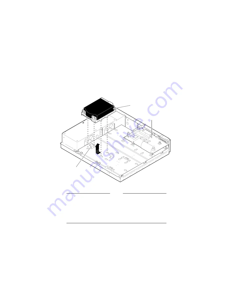
Removing Fixed Disk Drives
Figure 2–2 Removing RZ2x Fixed Disk Drives from the Drive
Plate
RZxx Hard Disk
Drive Plate
Lever
SCSI Mass Storage
Controller Module
MLO-010908
Note
If there are three disk drives on the drive plate, you
must remove the mass storage controller module from
the drive plate to remove the third drive. Otherwise, just
disconnect the cables going to the mass storage controller
to remove the drive plate from the system unit.
2–4 Removing Options from a Model 30 and 38 Workstation