background image

i

Important Safeguards

In addition to the careful attention devoted to quality standards in the manufacturing process of 
your video product, safety is a major factor in the design of every instrument. However, safety is 
your responsibility too. This sheet lists important information that will help to assure your 
enjoyment and proper use of the video product and accessory equipment. Please read them 
carefully before operating and using your video product.

Installation

1.

Read and Follow Instructions

 - All the safety and 

operating instructions should be read before the 
video product is operated. Follow all operating 
instructions.

2.

Retain Instructions

 - The safety and operating 

instructions should be retained for future reference.

3.

Heed Warnings

 - Comply with all warnings on the 

video product and in the operating instructions.

4.

Polarization

 - Do not defeat the 

safety purpose of the polarized or 
grounding-type plug.

A polarized plug has two blades 
with one wider than the other.

A grounding type plug has two 
blades and a third grounding prong.

The wide blade or the third prong 
are provided for your safety.

If the provided plug does not fit into your outlet, 
consult an electrician for replacement of the 
obsolete outlet.

5.

Power Sources

 - This video product should be 

operated only from the type of power source 
indicated on the marking label. If you are not sure of 
the type of power supply to your location, consult 
your video dealer or local power company. For video 
products intended to operate from battery power, or 
other sources, refer to the operating instructions.

6.

Overloading

 - Do not overload wall outlets of 

extension cords as this can result in the risk of fire 
or electric shock. Overloaded AC outlets, extension 
cords, frayed power cords, damaged or cracked wire 
insulation, and broken plugs are dangerous. They 
may result in a shock or fire hazard. Periodically 
examine the cord, and if its appearance indicates 
damage or deteriorated insulation, have it replaced 
by your service technician.

7.

Power Cord Protection

 - Power supply cords should 

be routed so that they are not likely to be walked on 
or pinched by items placed upon or against them, 
paying particular attention to cords at plugs, 
convenience receptacles, and the point where they 
exit from the video product.

8.

Ventilation

 - Slots and openings in the case are 

provided for ventilation to ensure reliable operation 
of the video product and to protect it from 
overheating. These openings must not be blocked or 
covered. The openings should never be blocked by 
placing the video equipment on a bed, sofa, rug, or 
other similar surface. This video product should 
never be placed near or over a radiator or heat 
register. This video product should not be placed in a 
built-in installation such as a bookcase or rack 
unless proper ventilation is provided or the video 
product manufacturer’s instructions have been 
followed.

9.

Attachments

 - Do not use attachments unless 

recommended by the video product manufacturer as 
they may cause a hazard.

10.

Camera Extension Cables

 – Check the rating of 

your extension cable(s) to verify compliance with 
your local authority regulations prior to installation.

11.

Water and Moisture

 - Do not use this video product 

near water. For example, near a bath tub, wash 
bowl, kitchen sink or laundry tub, in a wet 
basement, near a swimming pool and the like. 

Caution

: Maintain electrical safety. Powerline 

operated equipment or accessories connected to 
this unit should bear the UL listing mark of CSA 
certification mark on the accessory itself and should 
not be modified so as to defeat the safety features. 
This will help avoid any potential hazard from 
electrical shock or fire. If in doubt, contact qualified 
service personnel.

12.

Accessories

 - Do not place this 

video equipment on an unstable 
cart, stand, tripod, or table. The 
video equipment may fall, causing 
serious damage to the video 
product. Use this video product 
only with a cart, stand, tripod, 
bracket, or table recommended by the 
manufacturer or sold with the video product. Any 
mounting of the product should follow the 
manufacturer’s instructions and use a mounting 
accessory recommended by the manufacturer.

Summary of Contents for DND13TL2

Page 1: ...www digimerge com Copyright 2012 Digimerge Technologies Inc Instruction Manual English Version 1 0 DND13TL2 IR Mini Vandal Dome IP Camera...

Page 2: ...IED SERVICE PERSONNEL The lightning flash with arrowhead symbol within an equilateral triangle is intended to alert the user to the presence of uninsulated dangerous voltage within the product s enclo...

Page 3: ...ed by your service technician 7 Power Cord Protection Power supply cords should be routed so that they are not likely to be walked on or pinched by items placed upon or against them paying particular...

Page 4: ...can prevent fire electric shock or other hazards 16 Safety Check Upon completion of any service or repairs to this video product ask the service technician to perform safety checks recommended by the...

Page 5: ...al environment This equipment generates uses and can radiate radio frequency energy and if not installed and used in accordance with the manufacturer s instruction manual may cause harmful interferenc...

Page 6: ...Syncro V Power over Ethernet PoE operation 14Watt max 12V operation Backup options microSD card FTP NAS local Mobile Apps iPhone iPad Android Supports two way audio Compact size 4 x 2 Simple 2 screw...

Page 7: ...using UPnP in Windows 7 10 4 3 Finding the Camera s IP Address using Bonjour in Mac OS 11 4 4 Finding the Camera IP using the BNC Test Cable 12 5 Configuring Remote Connection 13 5 1 Connecting to a...

Page 8: ...nager 48 6 13 1 Group 49 6 13 2 User 50 6 13 3 Unlocking User Accounts 51 6 14 Protocol 52 6 14 1 Protocol 52 6 15 Device Restart 52 6 16 Default Settings 53 6 17 Sensor Configuration 53 6 17 1 Image...

Page 9: ...Start Guide 1 x Instruction Manual 1 x Software Documentation CD 1 1 Default Camera Username Password and Ports Username admin Password admin Ports 80 HTTP 30001 Control Streaming 8080 RTMP 554 RTSP I...

Page 10: ...n when camera is connected to power NET Middle Flashes red to indicate network activity BNC analog output microSD card slot max 64GB supported SanDisk Kingston brand memory cards recommended Status LE...

Page 11: ...e instructions This manual only covers hardware installation network setup and web browser configuration 1 3 1 Milestone XProtect Go Milestone XProtect Go is a fully featured client server solution pr...

Page 12: ...port visit www digimerge com 1 3 3 CMS DH PRO Digimerge CMS DH PRO is a client only solution that supports up to 16 IP cameras CMS DH PRO is a free software available on www digimerge com CMS DH PRO a...

Page 13: ...required NOTE Use the included RJ45 coupler to connect to male end of RJ45 Ethernet cable RJ45 Coupler 2 Audio Input RCA Connect to a self powered microphone for listen in audio 3 Audio Output RCA Con...

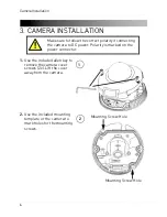
Page 14: ...screws 2x Lift the cover away from the camera 1 2 Use the included mounting template or the camera to mark holes for the mounting screws Mounting Screw Hole Mounting Screw Hole 2 Make sure to follow...

Page 15: ...ble into the video test cable terminals and connect to a test monitor to check the camera viewing angle BNC Test Cable 4 5 Optional Insert a microSD card into the camera To enable recording you must f...

Page 16: ...camera Tighten the screws when finished Loosen screws to adjust the angle of the ball camera Do not remove the screws holding the ball camera 6 IR LED NOTE Ensure the ball cameraispointedinthesame dir...

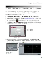
Page 17: ...ncro V 1 Install Syncro V from the CD or from www digimerge com Double click the Syncro V icon on the Desktop The log in screen appears 2 Under User Name and Password enter the default Syncro V user n...

Page 18: ...admin 6 The camera appears under the camera IP address Click and drag the camera to the display grid to open it Click and drag the camera to the display grid to open it NOTE For detailed instructions...

Page 19: ...the camera s User Name default admin and Password default admin and click Login Enter Camera User Name default admin Enter Camera Password default admin Click Login 4 3 Finding the Camera s IP Address...

Page 20: ...ord default admin and click Login Enter Camera User Name default admin Enter Camera Password default admin Click Login 4 4 Finding the Camera IP using the BNC Test Cable When the BNC test cable is con...

Page 21: ...ault 30001 NOTE If you are configuring multiple IP cameras for individual remote access you must change the ports for each camera Two cameras cannot use the same port number NOTE Port forwarding the R...

Page 22: ...lt admin and Password default admin and click Login 3 Click Device Info and write down the MAC Address MAC Address Step 4 of 6 Register for Digimerge DDNS Digimerge offers a free DDNS service for use...

Page 23: ...tion 3 Complete the System Information fields Product License Select your product model from the Product License drop down menu Product Code MAC Address Enter the camera s MAC address you recorded ear...

Page 24: ...eated your DDNS account e g tomsmith digimerge net User Name Enter the User Name you received in the confirmation email Password Enter the Password you received in the confirmation email 4 Click OK to...

Page 25: ...ager The Device Maintenance window opens Click Add Click Save Enter the camera s DDNS address Control Port 3 Under Device IP enter the Domain Name from the confirmation email For example enter tomsmit...

Page 26: ...lity to connect to the camera remotely 9 Click on the camera in Device List to login Enter the User Name default admin and Password default admin and then click Continue Click Continue Enter Camera Us...

Page 27: ...s IP address See 4 Finding the Camera s IP Address on page 9 2 Open your browser and enter the camera s IP address in the address bar in the following format http 192 168 0 120 80 Camera IP address Co...

Page 28: ...www adobe com to download the latest version After installing Flash Player restart your browser and reconnect to the camera 6 3 Internet Explorer Setup Step 1 of 2 Change Internet Explorer security se...

Page 29: ...the Camera s IP Address on page 9 2 Enter the camera s IP address in the address bar in the following format http 192 168 0 120 80 IP address Colon HTTP port number http NOTE You can also connect to...

Page 30: ...If your computer does not have Flash Player installed you will be promptedtoselectifyouwouldliketouseActiveXorFlashPlayertoconnect to the camera Click to play live video with ActiveX control to reduce...

Page 31: ...u You can right click on the live video area to bring up the Live Video Menu Right click on the video area to open the Live Video Menu Camera configuration menus Click and drag to zoom in Right click...

Page 32: ...page 53 ZoomIn Zoom in one level ZoomOut Zoom out one level Restore Panorama Zoom out all the way 6 4 2 Configuring Camera Settings Click the options on the left to configure camera settings Setting...

Page 33: ...List in Syncro V firmware version MAC address and camera inputs and outputs You can also configure the Device Name for your camera ATTENTION The device ID is unique Do not change it unless your instal...

Page 34: ...figure video streaming settings 1 Click Stream Configuration Under Stream ID select the stream you would like to configure 2 Configure the following Video Encode Type Select the Video Encoding type fo...

Page 35: ...ly to stream3 Bit Rate For stream1 or stream2 select CBR Constant Bit Rate or VBR Variable Bit Rate Enter the desired bit rate below in kbps Stream3 only supports VBR Quality Select the video quality...

Page 36: ...nt of a power failure To configure the camera s networking parameters 1 Click Device Configuration Local Network 2 Under IP Protocol select IPv4 or IPv6 If you would like to use IPv6 make sure it is s...

Page 37: ...http before the camera s IP address and colon and the HTTP port after the IP address when connecting using an Internet browser e g if the HTTP port is 85 enter http 192 168 x x 85 RTSP Port Default i...

Page 38: ...deo system frequency To change the Channel Name Configure the Channel Name as needed and then click the Set button next to Channel Name To change the video system frequency Select the desired setting...

Page 39: ...Under Time Zone select your time zone 3 If your region observes daylight savings time check Adjust clock for daylight saving changes Under Start and End select the start and end times for daylight sav...

Page 40: ...set the time and date 6 Click Apply The camera updates to the newly entered time 6 7 5 OSD The OSD page allows you to configure the camera s on screen display text To configure the camera OSD 1 Click...

Page 41: ...ges Text on row 0 is shown at the top of the screen and moves down as the row number increases Text on column 0 is shown on the left side of the screen and moves right as the column number increases R...

Page 42: ...n audio or un check to disable 3 Under Microphone Volume select the volume for the microphone between 1 100 4 Click OK to save changes 6 7 7 BNC Video Output Under BNC Output Device Configuration BNC...

Page 43: ...k Alarm The Disk Alarm page allows you to configure alarms if there is an issue with the recording disk You can configure a Disk Full Alarm or a Disk Error Alarm A Disk Full Alarm triggers an alarm wh...

Page 44: ...The Motion alarm page allows you to configure camera motion detection alarm settings You must enable motion detection to use local e g microSD SD card or FTP recording motion detection recording For i...

Page 45: ...l times during all 3 periods 5 Click Motion Area and configure up to 8 motion detection areas Select Area Motion or Area Mask to configure motion detection areas Area Motion allows you to select areas...

Page 46: ...allows you format the microSD SD card IMPORTANT You must format the microSD SD card using the camera before you can record to it To format the microSD SD card to enable recording NOTE Formatting the...

Page 47: ...System select SDVideo recommended or Ext3 7 Click Format A window will appear to show the status of the formatting Wait for the formatting to complete and then click OK NOTE If the Record Disk Path m...

Page 48: ...figure the following Check Enable Configure FTP server information Click OK IP Enter the FTP server address Port Enter the FTP port number Accounts Enter the FTP account user name Password Confirm Pas...

Page 49: ...e Syncro V or manually access your FTP server NOTE OntheRecordDirectorypage StatuswillbeOKwhenFTPisselected if FTP is accessible and all settings have been entered correctly Status OK To configure a N...

Page 50: ...e NAS e g public Accounts Enter the account user name for the NAS Password Confirm Password Enter the account password for the NAS File System Enter the NAS file system cifs or nfs Use All Space Check...

Page 51: ...6 9 1 Record Directory on page 38 To access your recordings use Syncro V or manually access your NAS device NOTE On the Record Directory page Status will be OK when NAS is selected if NAS is accessibl...

Page 52: ...e Record to create a schedule for recording If you select Schedule Record click Schedule and configure recording times The schedule is divided into 3 periods and the camera will record during all sele...

Page 53: ...can access video saved to FTP or NAS by manually accessing your FTP server or NAS device 6 10 Privacy Masking The Privacy Masking menu allows you to create up to 5 privacy areas that will not appear...

Page 54: ...onfiguring Remote Connection on page 13 To configure DDNS settings 1 Click Network Service DDNS 2 Check Enable DDNS 3 Configure the following Provider Select digimerge_ddns Domain Name Enter the Domai...

Page 55: ...Alert Setup The SMTP sub menu allows you to configure email alerts when motion alarms occur Email alerts will include a jpg snapshot attachment Before setting up email alerts you must configure the fo...

Page 56: ...ed to send email alerts Recipient E mail Address 1 5 Enter up to 5 email addresses that will receive email alerts Attachment Image Quality Select the quality of the image attachments High Mid or Low T...

Page 57: ...o add a user group 1 Click Add The Add Group menu appears NOTE If the Add Group menu does not appear disable any popup blockers 2 Enter a name for the user group and click OK Enter a group name and cl...

Page 58: ...elete a user group 1 Click Delete The Delete Group menu appears NOTE If the Delete Group menu does not appear disable any popup blockers 2 Select the group you would like to delete and click Delete 6...

Page 59: ...taneously or un check to limit the account to a single location at a time 5 Click OK to save the new user account To modify a user account 1 Select the user account under User and click Modify 2 Modif...

Page 60: ...rotocol contains the following sub menus Protocol Security Not supported NOTE Do not check User Verification in the Security sub menu as it may block ONVIF software from detecting the camera 6 14 1 Pr...

Page 61: ...ill reboot 6 17 Sensor Configuration The Sensor Configuration menu is used to adjust camera image settings To configure camera image settings using the Sensor Configuration menu Log into the camera us...

Page 62: ...vert all camera sensor settings to factory defaults Click Cancel to exit TIP Hold the mouse over the tabs to see the full name of the tab 6 17 1 Image Adjust Adjust the Brightness Saturation and Contr...

Page 63: ...ter speed when FixedShutter is selected 6 17 3 Gain Mode Select gain mode and adjust gain settings Gain Mode Select AutoGain or FixedGain MaxGain dB Select the maximum gain value when AutoGain is sele...

Page 64: ...ode or select Multicolor to have the camera remain in color during night mode 6 17 5 Auto Iris Set Auto Iris settings Auto Iris Select ON to enable or OFF to disable Iris Speed If Auto Iris is set to...

Page 65: ...is metered symmetrically Center Weighted When metering light priority is given to the center of the image Vertical Center Weighted When metering light priority is given to the vertical center of the...

Page 66: ...ttings for Digital Wide Dynamic Range Control Mode Select ON to enable Digital Wide Dynamic Range or OFF to disable NOTE Enabling Digital Wide Dynamic Range may cause color distortion based on the lig...

Page 67: ...rrorvertically orPictureFliptomirrorbothhorizontallyandvertically Select Close to disable image mirroring 6 17 11 Noise Filter Configure noise filter settings Noise Filter Select Auto for automatic no...

Page 68: ...et 1 1 Remove the camera cover screws 2x and remove the camera cover 2 Press and hold the white reset button for 5 seconds then release the button to reset the camera to factory defaults Press and hol...

Page 69: ...61 Dimensions 8 DIMENSIONS Units mm 99 9 49 2 52 9 30 3 100 0...

Page 70: ...tions 9 TECHNICAL SPECIFICATIONS Because our products are subject to continuous improvement Digimerge reserves the right to modify product design and specifications without notice and without incurrin...

Page 71: ...ot connected Camera is connected if you receive replies Connect the BNC test cable to the camera and the other end to a test monitor The monitor display shows the camera s IP address A default IP addr...

Page 72: ...s see 6 7 2 Device Port on page 29 for details on changing camera ports Can t connect to camera video on a web browser If using IE make sure to install ActiveX plug in or Adobe Flash Player For more i...

Page 73: ...om to receive product updates and information North America 1 866 816 5919 Technical support for technical installation issues Mon Fri 8 00 am to 8 00pm EST By Phone Product support is available 24 7...

Page 74: ......

Page 75: ......

Page 76: ...www digimerge com Copyright 2012 Digimerge Technologies Inc English Version 1 0 DND13TL2...

Reviews: