background image

Revision 1.0

3

Important Safeguards

Important Safeguards

In addition to the careful attention devoted to quality standards in the manufacture process of your video 
product, safety is a major factor in the design of every instrument. However, safety is your responsibility too. 
This sheet lists important information that will help to assure your enjoyment and proper use of the video 
product and accessory equipment. Please read them carefully before operating your video product.

Installation

1. 

Read and Follow Instructions - 

All the safety and 

operating instructions should be read before the 
video product is operated. Follow all operating 
instructions.

2. 

Retain Instructions - 

The safety and operating 

instructions should be retained for future reference.

3.   

Heed Warnings - 

Comply with all warnings on the 

video product and in the operating instructions.

4. 

Polarization -

 Do not defeat the safety purpose of 

the polarized or grounding-type plug.

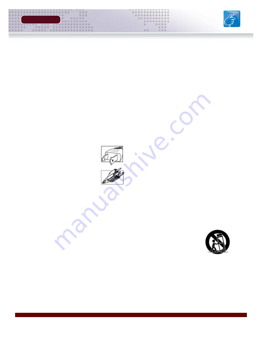
A polarized plug has two blades with 
one wider than the other.

A grounding type plug has two blades 
and a third grounding prong.

The wide blade or the third prong are 
provided for your safety.

If the provided plug does not fit into 
your outlet, consult an electrician.

5. 

Power Sources - 

This video product should be 

operated only from the type of power source 
indicated on the marking label. If you are not sure of 
the type of power supply to your location, consult 
your video dealer. For video products intended to 
operate from battery power, or other sources, refer 
to the operating instructions.

6. 

Overloading - 

Do not overload wall outlets with 

extension cords as this can result in the risk of fire 
or electric shock. Overloaded AC outlets, extension 
cords, frayed power cords, damaged or cracked wire 
insulation, and broken plugs are dangerous. They 
may result in a shock or fire hazard. Periodically 
examine the cord, and if its appearance indicates 
damage or deteriorated insulation, have it replaced 
by your service technician.

7. 

Power-Cord Protection - 

Power supply cords should 

be routed so that they are not likely to be walked on 
or pinched by items placed upon or against them, 
paying particular attention to cords at plugs, 
convenience receptacles, and the point where they 
exit from the video product.

8.   

Ventilation - 

Slots and openings in the case are 

provided for ventilation to ensure reliable operation 
of the video product and to protect it from 
overheating. These openings must not be blocked 
or covered. The openings should never be blocked 
by placing the video equipment on a bed, sofa, rug, 
or other similar surface. This video product should 
never be placed near or over a radiator or heat 
register. This video product should not be placed in 
a built-in installation such as a bookcase or rack 
unless proper ventilation is provided and the video 
product manufacturer’s instructions have been 
followed.

9. 

Attachments - 

Do not use attachments unless 

recommended by the video product manufacturer as 
they may cause a hazard.

10. 

Water and Moisture - 

Do not use this video product 

near water. For example, near a bath tub, wash bowl, 
kitchen sink or laundry tub, in a wet basement, near 
a swimming pool and the like. 

Caution: Maintain electrical safety. Powerline 
operated equipment or accessories connected to 
this unit should bear the UL listing mark of CSA 
certification mark on the accessory itself and should 
not be modified so as to defeat the safety features. 
This will help avoid any potential hazard from 
electrical shock or fire. If in doubt, contact qualified 
service personnel.

11. 

Accessories

 - Do not place this video equipment 

on an unstable cart, stand, tripod, or table. The video 
equipment may fall, causing serious 
damage to the video product. Use 
this video product only with a cart, 
stand, tripod, bracket, or table 
recommended by the 
manufacturer or sold with the video 
product. Any mounting of the product 
should follow the manufacturer’s 
instructions and use a mounting accessory 
recommended by the manufacturer.

Summary of Contents for DNB6300V

Page 1: ...Copyright 2007 Digimerge Technologies Inc HARDWARE MANUAL English version 1 0 DNB6300V DNB6300V Networkable Camera...

Page 2: ...persons The exclamation point within an equilateral triangle is intended to alert the user to the presence of important operating and maintenance servicing instructions in the literature accompanying...

Page 3: ...icates damage or deteriorated insulation have it replaced by your service technician 7 Power Cord Protection Power supply cords should be routed so that they are not likely to be walked on or pinched...

Page 4: ...e video product manufacturer can prevent fire electric shock or other hazards 16 Safety Check Upon completion of any service or repairs to this video product ask the service technician to perform safe...

Page 5: ...nnected z Consult the dealer or an experienced radio or television technician for assistance DIGIMERGE TECHNOLOGIES INC http www digimerge com NOTE This equipment has been certified and found to compl...

Page 6: ...rifocal DC Iris Lens Included IR Cut Filter IR LED Array with 330 ft 100 6M IR Range Built in Blower Heater Vandal Resistant Weatherproof IP66 Compliant Housing Multi Channel NVR Viewing Recording Sof...

Page 7: ...Hardware Installation Optional GPIO Connections 18 C Adjusting the Included Lens 18 D Software Installation Overview 19 Section 4 NETWORK CONNECTIVITY 21 29 Network Connectivity Overview 22 Locating...

Page 8: ...etwork 33 Management 33 Other 33 Appendix 2 Mini DIN GPIO Cable 34 35 GPIO Pin Out Configuration 34 Features and Specifications of the GPIO Solid State Relay 35 Appendix 3 Changing the Camera Network...

Page 9: ...GETTING STARTED SECTION 1 Package Contents 10...

Page 10: ...TO CONFIRM THAT YOU HAVE RECEIVED THE COMPLETE SYSTEM INCLUDING ALL COMPONENTS SHOWN ABOVE Software CD Quick Installation Guide Hardware Manual Housing Manual 3 ft Ethernet Cable 1 x Heavy Duty Metal...

Page 11: ...PRODUCT OVERVIEW SECTION 2 DNB6300V Connector Ports 12 DNB6300V Power Ports 13 DNB6300V Lens Adjustment 14...

Page 12: ...OWER NET STATUS LED INDICATORS The Red PWR LED indicates the Power state of the Camera ON OFF The Green NET LED indicates the Network state of the Camera The LED will blink when network communication...

Page 13: ...ctions on power connections 1 COOLING FAN POWER CABLE Provides power to the rear cooling fan on the Camera NOTE Do not disconnect this cable or the camera may overheat 2 IR SENSITIVITY ADJUSTMENT Set...

Page 14: ...with this camera which has been carefully selected to provide the best possible image quality As the lens mount is a CS Type there is an option to use any other type of CS Mount Lens however the inclu...

Page 15: ...INSTALLATION SECTION 3 Installation Overview 16 20 Hardware Installation Power 16 Hardware Installation GPIO 18 Adjusting the Included Lens 18 Software Installation Overview 19...

Page 16: ...ting the hard wired power and connecting the Ethernet cable to the Camera Other connections are optional NOTE The cables should be run through the wall or ceiling to the mounting location prior to ins...

Page 17: ...abelled ports Live Earth and Neutral Tighten the screws to hold the wires in place NOTE Please refer to the included INFRARED ILLUMINATOR HOUSING insert for additional details 4 Network Connect the ne...

Page 18: ...ck below the bracket once complete NOTE The GPIO Block is color coded and labelled Please see Appendix 2 for Alarm Block connections C Adjusting the Included Lens Use the ZOOM and FOCUS controls on th...

Page 19: ...Installs DigiConsole and Surveillance application on your local PC Warranty information and DDNS registration DigiViewer Runs on the IP Device This application resides on the IP Product and is loaded...

Page 20: ......

Page 21: ...K CONNECTIVITY SECTION 4 Network Connectivity Overview 22 Locating the MAC and IP Address 23 Router Port Forwarding 24 Setting Up Your DDNS Account 25 26 DigiViewer DDNS Setup 27 Remote Access with IE...

Page 22: ...h using an Ethernet Cable and power on the Camera NOTE The Camera must be connected to the router prior to connecting the power to the IP Device 2 Locate the MAC and IP address of your Camera using th...

Page 23: ...een display NOTE You may need to press the Find Devices button several times as some devices may not respond immediately If you do not see a snapshot image please check that all cables running to the...

Page 24: ...om the Internet the information is sent to the Router When a computer on the Internet needs to send data to your internal network it sends this data to the external IP address of the Router The Router...

Page 25: ...a A DDNS account allows you to set up a web site address that points back to your Local Network The following outlines how to set up your free DNS account 3 Complete the Account Information fields wit...

Page 26: ..._______________________________________________ User Name _________________________________________________ Password __________________________________________________ Domain name User name Password...

Page 27: ...ation will load in the default Web Browser A Click on the SETTINGS link B Click on the NETWORK SERVICES link C Enter the DDNS information received in the DDNS Confirmation Email z Check Enable Digimer...

Page 28: ...nside the Local Network the Remote IP i e http 72 154 89 164 or DDNS Address http myurl digimerge net for the remote IP Device Internet Explorer Security Warnings Several security warnings may appear...

Page 29: ...information to be installed to your PC Click the Install button to allow the ActiveX controls to be setup on the PC Internet Explorer Security Warnings Windows Firewall The Digimerge IP Devices requi...

Page 30: ......

Page 31: ...Appendix 1 Camera Specifications Appendix 2 COM GPIO Terminal Block Appendix 3 Changing the Network Appendix 4 Hardware Reset Other Digimerge IP Products Digimerge Limited Warranty APPENDICES...

Page 32: ...necting to a CCTV monitor DVR etc 1 x Internal Microphone 1 x DC iris power connector 2 x LEDs to indicate network and power system status internal 1 x AC Terminal Block Lens Standard Package CS Mount...

Page 33: ...RHG Network Network Interface 10 100 Base T Ethernet Protocols TCP UDP IP IMCP HTTP FTP SMTP DHCP NTP DNS DDNS RTSP RTP TCP UDP Network Management Other Power Consumption 20W inc IR Fan Unit Dimensio...

Page 34: ...when opening the connection input low when sinking more than 10mA or shorting to pin 5 GND 2 RXD COM Port Receive Data 3 TXD COM Port Transmit Data 4 RS485 A Connect an external PTZ or Alarm device F...

Page 35: ...erse Voltage Continuous Forward Current Peak Forward Current Power Dissipation Derate Linearly from 5 0V 50mA 1A 100mW 25 C 1 3mW C Emitter Input Output Breakdown Voltage Continuous Load Current Power...

Page 36: ...is information can be changed however incorrect changes to these settings will prevent access to the device and a Hardware Reset will be required 1 IP Address Port The IP address and port assigned to...

Page 37: ...re Close the browser To access the device again refresh the browser after 30 seconds NOTE This will not reset Networking and Account Settings Hardware Reset To Restore Factory Defaults from the Hardwa...

Page 38: ...Digimerge IP Products SECTION 5 38 HARDWARE MANUAL Copyright 2007 Digimerge Technologies Inc Digimerge IP Products...

Page 39: ...ment date or the remainder of the warranty term whichever is longer Repairs are warranted for 90 days outside the original warranty period Products and parts at Digimerge s sole discretion may be repl...

Page 40: ...tion of the applicable written warranty and if damages may not be limited then the above limitations on damages apply but only to the greatest extent permitted by local law Warranty and Non Warranty S...

Page 41: ...It s all on the web Product Information User Manuals Quick Start Guides Specification Sheets Software Upgrades Firmware Upgrades Digimerge Technologies Inc VISIT www digimerge com www digimerge com...

Page 42: ......

Reviews: