background image

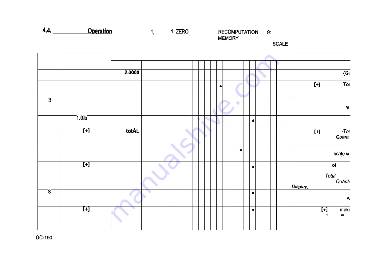
 Accumulation

 When Spec 32 bit

Default Setting, (Auto Exit when Accumulation) is 

enabled, The Scale will automatically go back to weight 

mode after the Accumulation. 

2; TARE 

3: GROSS 

4: INSUFFICIENT 

5:
6:
7: PROG 

• 8: KG 

 LB 

10: BATTERY LOW 

11:

 1 

12: SCALE 2 

13: SCALE 3 

14: SCALE 4 
15: IN 
16: OUT 

S/No. 

OPERATION 

DISPLAY 

INDICATORS 

REMARKS 

S/No. 

OPERATION 

WEIGHT 

UNIT 

WEIGHT 

QUANTITY 

1  2  3  4  5  6  7 

8  9  1 


200.00 

10 

• 

After Unit Weight entry.
4.3) 

tOtAL 

10 

• 

Press the

 key. The

is displayed in the Quant 
Display. 

2.0000 

200.00 

10 

• 

• 

• 

The memory lamp will glow 
After a moment the scale

resume operation mode. 

Put

 on the 

platter 

3.0000 

200.00 

15 

• 

25 

• 

• 

Press the

 key. The

is displayed in the
Display. 

3.0000 

200.00 

15 

• 

The memory lamp will glow 
After a moment the

resume operation mode. 

Total 

40 

• 

The previous total

 25 ar 

the present quantity of 15 a 

added and the

 Of 40 

displayed in the

3.0000 

200.00 

15 

• 

• 

The memory lamp will glow 

After a moment the scale

resume operation mode. 

totAL 

55 

• 

Pressing the

 key

the total 15

 40

 5 

displayed in the Quanti 

Display. 

 OPERATION MANUALREV03.DOC 

14 

All manuals and user guides at all-guides.com

Summary of Contents for DC-190 ULTRA COUNT

Page 1: ...MATEX 80 OAK 07648 FAX www dfgjmatex com 1ST AUGUST 1998 2ND OCTOBER 1998 3RD JANUARY 1999 4TH OCTOBER 1999 5TH 6TH All manuals and user guides at all guides com ...

Page 2: ...All manuals and user guides at all guides com ...

Page 3: ...w Code Normal Inventory Operation 5 0 PROGRAM MODE 5 1 Data setting Programming Id Code 200 Item 5 2 Set Point Programming Set Point Programming by Quantity 24 5 1 2 Set Point Programming by Weight 25 Set Point Programming by Upper Lower Limit Quantity 5 1 4 Set Point Programming by Upper Lower Limit Weight 27 Set Point by Weight or by Quantity 5 3 Check item Code in Memory 29 5 4 Item Memory 30 5...

Page 4: ...t the goods sold be free from defects in workmanship and materials normal operating conditions At option INC will repair or without charge any goods which it finds to be defective in either workmanship or provided that MATEX INC has been notified by the buyer of the defect prior to the termination of the warranty period and the goods are shipped to DIGI MATEX INC with its authorization and with al...

Page 5: ...1 3 Appearance 1 4 Keyboard 5 5 3 RE ZERO OPERATION 3 All manuals and user guides at all guides com ...

Page 6: ... being accumulated or when memory overflows Prog When in the programming mode with MODE key pressed Kg When the item is in Kg unit with Kg Lb key pressed Lb When the Item is weighed in Lb unit with key pressed Batt When power level is Scale 1 When Scale 1 is used Scale 2 When Scale 2 is used Scale 3 When Scale 3 used Scale 4 When Scale 4 is used IN Inventory In OUT Inventory Out OPERATION V03 DOC ...

Page 7: ...numeric keyboard MODE Used for entering mode from weighing SCALE Used to switch between scales Used for Accumulation and for incrementing SPEC numbers in SPEC setting Also used to program set in programming mode Used for and for decrementing SPEC numbers in SPEC setting mode Also use to program Part No in programming item Programming mode it can be used for viewing or setting date time Used for st...

Page 8: ... Part No PrESS Calibration Mode Press Code Key to Zero Mode rtem Set Point rS232 ConErr RS232 Span Switch is On Sat Saturday SEt P Set X Set Number Spec Number SUn Sunday TArE Tare tArE Tare Is Not Allowed Since Weight 0 XX Teraoka Code Character Position Character Code Character THU Thursday XXXXXXX or Subtracting Operation TUE Tuesday UF Underflow Unft Unit Weight is Out Of Range on the high sid...

Page 9: ... 00 SPACE 20 T 40 A 21 41 02 B 22 V 42 03 C w 43 04 D 24 X 44 05 E 25 Y 45 06 F 26 z 46 07 G 27 47 H 48 09 I 29 49 10 J 0 50 11 31 1 12 L 32 2 13 M 33 3 14 N 34 4 15 35 5 16 P 36 6 17 37 7 18 38 8 19 S 39 9 DC 190 OPERATION 7 All manuals and user guides at all guides com ...

Page 10: ...th 0 005 0 00005 100 0 lb Both 0 0001 PC 192D Dual Scale Capacity Scale 1 Scale 2 Platform Bulk Platform 0 5000 5 0000 x 6 1 0000 5 0000 1 0000 10 000 1 0000 25 000 x 6 12 1 0000 50 000 x 2 5000 2 5000 25 000 x 2 5000 50 000 Remote Platforms Platform capacity ht Counting Resolution Resolution Dimensions 0 02 0 0002 500 00 0 05 0 0005 1000 0 0 1 0 001 X 0 2 0 002 5000 0 0 5 0 005 X 1 0 0 01 x or x ...

Page 11: ...uture shipment of the scale is required 3 2 Inspection Immediately after a visual inspection of the should be performed If any damage has been incurred during transportation notify the shipper and DIGI MATEX INC immediately Instructions for of damage and further procedures will then be determined If at anytime the counting scale must be returned for modification calibration or repair be sure that ...

Page 12: ...DC 190 OPERATION EV03 DOC All manuals and user guides at all guides com ...

Page 13: ...5 Lb weight the platter 0 5000 0 0 3 0 0000 0 0 Press the TARE key to the weight on the platter Bi 0 and 1 in Spec 27 must to appropriate tare value 4 Remove the weight from the platter 5000 0 0 tare S No DISPLAY INDICATORS REMARKS WEIGHT UNIT WEIGHT QUANTITY 1 2 3 4 S 6 7 8 9 1 0 1 1 1 2 1 3 1 4 1 5 1 6 1 0 0000 0 0 Display in the weighing mode 2 0 5000 3 0 0 Press the key to tare the weight ente...

Page 14: ...0 0 Display in the weighing mode 2 0 5 Lb weight on the 0 5000 0 0 3 TARE 0 0000 0 0 Press the TARE key to tare the weight on the platter Bit 0 and 1 in Spec 27 must be set to appropriate value 4 0 5 the platter 0 5000 0 0 5 NET 1 0000 Press the NET GROSS key 1 0000 lb is the Gross Weight Spec 25 0 must be set to 6 NET GROSS 0 5000 0 0 Press the NET GROSS key 0 5000 lb is the Net Weight OPERATION ...

Page 15: ... sample pieces are placed on the platter add a few more pieces Insufficient lamp is Enter the no of pieces using the keyboard and the PIECES key For example After putting ten on the scale as a sample the insufficient lamp is add a few more pieces ex 3 until insufficient lamp is Now using the keyboard enter and then press the PIECES key to compute the unit weight of the samples 4 3 2 Weight Operati...

Page 16: ...Press the key The is displayed in the Quant Display 2 0000 200 00 10 The memory lamp will glow After a moment the scale resume operation mode 4 Put on the platter 3 0000 200 00 15 5 25 Press the key The is displayed in the Display 6 3 0000 200 00 15 The memory lamp will glow After a moment the resume operation mode 7 Total 40 The previous total 25 ar the present quantity of 15 a added and the Of 4...

Page 17: ...move the 2 0 lb Weight from platter 1 0000 200 00 5 Leave only the 1 weight on the 4 H totAL 65 Pressing the deducts the quantity of 5 in the Quantity Display from the previous Total of 70 to give us à total of 5 1 0000 200 00 5 The memory lamp glow After a the scale will operation mode 6 H totAL 60 Press key The total quantity after subtracting is shown in the Quantity 65 60 7 1 0000 200 00 5 mem...

Page 18: ... key clears the accumulated 4 7 Unit 5 13 SCALE3 2 TARE 6 MEMORY 10 BATTERY LOW 14 SCALE 4 3 PROG 11 1 15 IN 4 INSUFFICIENT 8 KG 12 SCALE 2 OUT S No OPERATION DISPLAY INDICATORS REMARKS WEIGHT UNIT WEIGHT QUANTITY 1 2 3 4 S 6 7 8 9 1 0 1 1 1 2 1 3 1 4 1 5 1 6 1 200 00 0 Remove weight 2 CLEAR 0 0000 0 0 Pressing the CLEAR key clears the unit weight DC 190 OPERATION MANUALREV03 DOC 16 All manuals an...

Page 19: ...essing the SCALE key again changes back to Scale 1 Note Default Position The Position for Scale 1 to scale 4 be set in Spec Scale Internal Scale 1 Scale 3 External Scale Scale 2 Internal Scale 2 Scale 4 Force Balance ONLY SCALES PRESENT WILL BE SELECTED EX 2 SCALE SYSTEM SWITCHES BETWEEN SCALE 1 AND 2 ONLY 4 9 Recall The Item Recall The Item For Normal Operation OPERATION DISPLAY INDICATORS REMARK...

Page 20: ... Teraoka Code 00 01 A CODE Enter 4 Press or to shift right or left position t C 01 oo CODE press key 5 Input 2 digit Teraoka Code 01 03 C CODE Enter 6 Press or to shift to right or left position t c 02 00 CODE press key 7 Press CODE to call the PLU 50 100 0 4 10 Unit In Memory S No OPERATION DISPLAY CATORS REMARKS S No OPERATION WEIGHT UNIT QUANTITY 1 2 3 5 6 7 8 1 0 1 1 1 2 1 3 1 4 1 5 1 6 1 Reca...

Page 21: ...ORS REMARKS S No OPERATION W E I G H T UNIT W E I G H T QUANTITY 1 2 3 4 s 6 7 9 1 0 1 1 2 1 3 1 4 1 5 1 6 1 Press new code no 246 If Spec 3 bit 2 3 is set 16 Digit Teraoka Code can be entered by pressing key Please refer to 4 9 2 2 Press CODE key 246 F 3 Press CODE key to set the new code no Into memory 0 0 0 4 Enter unit weight See pg 13 4 3 2 0 200 0 5 Press the UNIT WEIGHT key enter into memor...

Page 22: ...until IN is lit 2 1234 3 CODE 2 0000 0 4 Weight on the X XXXX 2 0000 X XXXX 5 0 0 Renew IN by adding the Quantity 6 Remove Weight and press key 0 0000 0 0 Depress CODE key until Indicator OUT is lit 7 1234 CODE 0 0 9 Weight on the platter 10 0 0 Renew by deducting the Quantity 11 Remove weight and press 1234 12 CODE 0 0000 0 0 13 Press NET Key XXX Check Quantity in Stock 14 Press NET GROSS Key 0 0...

Page 23: ...ge the mode ProG C 0 2 Enter code no 1 2 3 ProG 123 If Spec 3 bit 2 3 is set 16 Digit Teraoka Code can be entered by pressing key Please refer to 4 9 2 3 Press CODE key 0 0 0 4 Put sample parts on the scale platter e g 10 PCs 0 0 5 Enter sample quantity 10 Press key 2 200 10 7 Press key to set the unit weight into the memory ProG C 1 LB 13 SCALE 3 10 BATTERY LOW 14 SCALE 4 11 1 IN 12 SCALE 2 16 OU...

Page 24: ...ter code no 1 2 ProG Spec 3 bit 2 3 is set Digit Teraoka Code can entered by pressing key Please refer to 4 9 2 3 Depress CODE key 0 0 0 4 Enter Unit Weight 100 100 Program Unit Weight 5 Press UNIT Key 0 100 0 6 Enter Tare Value 50 Program Tare 7 Press key 50 0 0 8 Press NET GROSS key For Quantity in Stock 0 InVEnt Program Quantity in Stock 9 Enter Quantity Number 68 InVEnt 10 Press NET GROSS key ...

Page 25: ...heck set point 1 Depress key to check set point 2 Depress key to Store the set Point Depress to Store the part setting 00 t C 00 t C 01 50 2 ProG 1234 100 00 00 100 200 no P nAmE 500 90 8 KG LB 10 BATTERY LOW 1 12 SCALE 2 13 SCALE 3 14 SCALE 4 16 OUT Please Note Part No can be programmed using Teraoka Code selecting by Spec The programming method Is same with Name Programming expect when storing t...

Page 26: ...ogramming mode 3 M 0 Press key to go into Set Poir Programming Mode 4 1 0 0 0 0 10000 Enter the Quantity for Set Point using the Numeric 5 CLEAR 2 0 Using the CLEAR th key 6 7 5 2 75 Enter the new Set Point 2 valu using the Numeric keys 7 ProG 0 Pressing the key exits fror the Set Point Programming but remains in the 8 MODE 0 0000 0 0 Pressing the MODE key exit from Programming mode returns to Wei...

Page 27: ...or Set Point 1 using the Numeric keys depending on the capacity of the scale Please see the note below 5 0 Press the key to program Set Point 2 6 2 50 75 Enter the value for Set Point 2 using Numeric Please see the note below 7 M ProG Pressing the key exits from the Set Point Programming mode but remains in the Programming 8 MODE 0 0000 0 0 Pressing the key exits from Programming mode and returns ...

Page 28: ... 6 7 8 9 1 0 1 1 1 2 1 3 1 4 1 5 1 6 1 0 0000 0 0 Display in the weighing mode 2 MODE C 0 Press the MODE key to go into the programming mode 3 0 Press key to go into Set Point Programming Mode 4 20000 Enter the Quantity value for Set Point 1 using the Numeric keys Please see the note below 5 2 0 Press the key to program Set Point 2 6 2 10000 Enter the Set Point 2 value using the Numeric keys Pleas...

Page 29: ...Mode 4 raiJ 0 0 0 0 SEt 1 3 0000 Enter the upper weight value for Set 1 using the keys depending on the capacity the scale Please see the note 5 2 0 Press the key to program Set Point 2 6 2 2 0000 Enter the lower weight value for Set Point 2 using Numeric keys Please see the note below 7 ProG C 0 Pressing the key exits from the Set Point Programming mode but remains in the Programming mode 8 MODE ...

Page 30: ...mming Mode 4 2 0000 Enter the Weight value for Set Point 1 using the Numeric keys depending on the capacity of the scale Please see the note below 5 M 2 Press the key to program Set Point 2 6 2 3 0000 Enter the weight value for Point 2 using Numeric keys Please see the note 7 ProG C 0 Press the key to program setpoint 3 through 6 or exits from the Set Point Programming on spec but remains in the P...

Page 31: ...UT S No OPERATION DISPLAY INDICATORS REMARKS UNIT QUANTITY 2 3 4 5 6 7 1 1 2 1 3 1 4 1 5 1 6 1 Press MODE key ProG C XX 2 Press CODE key 1 123 Press key to check entered CH 2 246 4 CH 3 345 5 Press key to check entered code prior CH 2 246 6 Press MODE key to return to the step ProG C XX DC 190 OPERATION All manuals and user guides at all guides com ...

Page 32: ...key ProG C 10 2 Enter 0 while pressing REZERO key ALL CLEAr 3 Press CLEAR key to complete deletion of all memories ProG C 0 N o t e Delete All Quantity In Stock Press Delete All Item Unit Weight Press Delete All Item Tare Weight Press M Delete All Item Part Number Press Delete All Item Set Point Press M Delete All Item Name Press Reset SEQ No Press Use for Printer BCP 30 Delete Alt Set Point Not I...

Page 33: ... 3 4 5 6 7 S 9 1 0 1 1 1 2 1 1 4 1 5 1 6 1 Press key ProG C XX 2 Press Key 09 12 98 TUE 12 01 the date and time 3 Press Key 0 4 Enter Day and Year Enter Program the date 5 Press key 0 Program the day 6 Enter Day Un 0 6 7 Press key EntEr tlmE 0 8 Enter EntEr tlmE 1401 Program the time 9 Press key to store the setting OR press key to bypass the ProG C XX DC 190 OPERATION All manuals and user guides ...

Page 34: ...QUANTITY 156141 INDICATORS 8 REMARKS Enter while pressing the REZERO key The display will show Weight in the Weight and Zero Count in the The zero count should be Press the CODE key in order to compute the zero point It takes a few seconds for the zero calibration 3 6195 93234 0 ÛÛÛ0 After computing the zero point the Quantity Display shows the Zero Ensure that counts are 100 000 10000 repeat Step...

Page 35: ...1 5 1275 is closer than 4 7997 Example 4 9124 is closer than 5 3985 TO ADJUST THE SPAN PRESS PIECES OR TARE IF THIS PROCEDURE IS NOT DONE PROPERLY THE SCALE MAY APPEAR 7 AND REPEAT STEPS 2 THROUGH 8 Place 5lb weight on platter 5 2715 0 580397 Place weiaht of 5lb or any weiaht on the In this is used as an 9 5 2715 5 0000 580387 Enter the weight placed on the platter using the Numeric Keys 10 Press ...

Page 36: ...ty Display the Zero starting point 1 Internal Count is set to the count should be around If the zero point is not correct please carry out the calibration procedure again MODE ProG C XX Pushing the MODE key once exits calibration mode 14 MODE 0 0000 Pushing MODE key once more returns the scale to the weighing mode Please Note Pressing CODE key step 2 is for auto finding the zero Customer can manua...

Page 37: ...01 1011 0000 Enter 1011 the value for SPEC01 using the Numeric keypad 5 CLEAR SPC01 0000 CLEAR key clears the entry 6 SPC02 0000 key increases to the next SPEC number 7 SPC01 1011 decreases to the previous number 8 H spcoo 0000 decreases from SPEC 01 to 00 9 SPC19 0000 key decreases the SPEC number from SPEC00 to 19 10 PROG C 00 stores the new SPEC values to the and exits from the SPEC setting mod...

Page 38: ...EC data in the RAM location 3 SPC21 1011 Enter as the new value for PEC21 using the Numeric keypad 4 CLEAR SPC21 0000 CLEAR key clears the Numeric entry 5 SPC22 0000 key increases to the next number 3 SPC21 1011 key decreases to the previous SPEC number 7 H SPC20 0000 decreases from SPEC 21 SPEC 20 SPC36 key decreases the from SPEC20 to SPEC36 NOTE When making any spec changes it is necessary to f...

Page 39: ...ount And 5 RECOMPUTATION 9 LB 13 SCALE 2 TARE 6 MEMORY 10 BATTERY LOW SCALE 4 3 GROSS 7 PROG 11 SCALE 1 15 IN 4 INSUFFICIENT 8 KG 12 SCALE 2 16 OUT S No DISPLAY CATORS REMARKS WEIGHT WEIGHT QUANTITY 1 2 3 4 S 6 7 8 9 1 Û 1 1 1 2 1 3 1 4 1 1 6 1 REZERO 88888 888888 2 REZERO 0 200000 Enter while depressing the REZERO Unit Display will display the Count and the Quantity Display will display the Count...

Page 40: ...d 4 Set New Code during Mode Extent of lclent samples Counting 1 Yes 5 1 1 time for it Weight Calculation times 1 times Unit Wt Auto Recomputing Date Order 00 Year Date 01 Date Year 11 Month Year 1 Accuracy of Unit Weight 0 No 1 Yes Clear All Kay rn One Touch 1 No RS232 Continue Sending 1 Low Auto Position After Key of Teraoka Code Entry 0 No 1 Yes 7 0 0 0 0 Set Point Buzzer 1 No Set 0 Latch No La...

Page 41: ...1 2400 11 15 RS 232C BCP Stop Bit Optional bits RS232C BCP With Header Bit Optional No Used 11 16 17 SHOULD ONLY BE BY AN AUTHORIZED TECHNICIAN III Set 0001 1 00 Scale 1 01 Internal Scale 2 10 External 11 Balance SCALE 2 Scale 1 01 Scale 2 10 External Scale 11 Force Balance Set 1011 SCALE 3 00 Internal Scale 1 01 Internal Scale 2 10 External 11 Balance SCALE 4 00 Scale 1 01 Internal Scale 2 Extern...

Page 42: ...ow or No 1 1 1 Net Battery 0 0 0 0 V 1 No 25 Type Gross Mode Method protected by 0 Single Available 0 Span Scale Yes 1 Manual 1 Double 1 No i 1 Scale Zero Tracking Weight Reset Initial Start Range When Tare when Tare Unlimited 10 FS Yes 0 0 0 0 1 No 1 01 11 Not Avail Comma Digital Tare Tare Range Display Setting 0 No 1 0 No Yes 01 Not Auto Tare clear Automatic Weight Clear Automatic Unit Condition...

Page 43: ... 0 0 0 0 For Scale 1 Normal Load Cell 1 For abnormal load cell with too 1 00 01 Prevent from Small tion fast change in display 10 Prevent from Medium vibration 11 Prevent Large in display 35 For Scale 2 Normal Load Cell 1 For load cell with too large offset Board r Scale 2 00 Normal 01 Prevent from Small Prevent from from Large slow change in display 36 0 0 Minimum Display Scale 3 01 Board For 00 ...

Page 44: ... PC is a secondary port option and is controlled by the port option selected in spec the primary option selected in spec 13 assumes its port and the PC assumes the remaining port 13 CONNECTOR Header Sub Din 0 Code 000 Force 001 Force Bal Printer Title 100 PC Force Bal 0 0 0 1 101 010 Printer PC PC SPEC 13 SUB CONTROL S P E C S SUB CONTROL SPECS DIN 000 Printer Force Bal 1 0 11 8 9 F B 001 Force Ba...

Page 45: ... Spec 11 Bit 0 1 Stop Bit 1 b i t 2 bits Spec 11 3 TO PC OUTPUT DATA FORMAT A With Header 12 0 set to 0 HEADER DATA CR HEADER CR LF One Data consists of must be added at the end of the data must be added at the end as a termination code of the There are two type of Headers Header Code ii Title 43 All manuals and user guides at all guides com ...

Page 46: ...OSS WEIGHT B 42 Status STATUS Status C 43 Date DATE TIME Date F Set Point 1 W Set Point ï G 47 Set Point 1 Q Set Point 1 Q H 48 Set Point 2 P2 Set Point 2 49 Total Quantity TOTAL QUANTITY Quantity K 4B Inventory INVENTORY M 4D Part No NO Part N 4E Part Name PART NAME Part Name V 56 No SCALE NO Scale Q 51 Set 3 SET P3 Set 3 X 58 Set Point 4 SET P4 Set Point 4 U 55 Set Point 5 Set Point 5 4F Set 6 S...

Page 47: ...rcentage Variable length Max 5 digits and 1 decimal or Lower Weight Variable length Max 5 digits and 1 decimal point or Lower Quantity length Max 7 digits 4 set point 1 and set point 2 can be sent as SET 1 SET Quantity Percentage Weight Percentage Upper Weight Lower Please Note Set Point 2 to 6 must either increase or decrease The decimal point for weight must be correct Gross Variable Max 5 digit...

Page 48: ...tput by key Others 5 Output by key Others Always setto 7 set to When bit 3 Output entered data is 1 bit 2 weight stable should be ignored Part No 12 digits Part Name 16 digits Scale No digits Date Header YEAR MONTH DATE HOUR MINUTE SEC CR 2 DIGIT 2 2 DIGIT 2 2 2 DIGIT 46 Status The status data byte is as follows All manuals and user guides at all guides com ...

Page 49: ...onal 10 11 11 RS 232C Stop Bit Optional 0 bit 1 2 bits PRINTER 0 LP2622 BCP 30 Parity Bit Optional 00 No Used 01 Odd 11 12 RS 232 Output 00 Not Available 01 When Courting Condition Key 11 In Both Cases 0 With Handshaking Without Header 1 No 13 Header Code Title RS232 OR Sub Din 000 Printer Force Bal Force Printer 100 Force Bal 101 Force Bal 010 Printer 011 Printer USA Default 10 0111 0100 SPEC12 0...

Page 50: ...3 Three Bar Code 190 can read Three lines bar code Ver D2 14 must be with header Line 1 Header Space Datai CR Line Space Data2 CR Line 3 Data3 CR Communication in OPERATION mode UNIT TARE PART CODE QUANTITY Communication available is P R O G R A M mode PART C O D E PART PART NAME INVENTORY WEIGHT TARE SET P O I N T S Bar Code Scanner DC190 can support RS232 Pen ZB800 Can Support Up to 16 digits La...

Page 51: ...t 6 6 6 4 4 Z Command Z Command Functions as REZERO Z6 CLEAR Z1 PRINT SCALE 1 Z2 UNIT WEIGHT CLEAR ZS2 SCALE 2 Z3 PLUS ZS3 SCALE 3 Z4 ZS4 SCALE 4 Z5 TARE 6 6 4 5 RS232C Related List The following spec must be set correctly in order for DC 190 to communicate the Scanner 14 RS 232C RS 232C Baud Rate Data Length Optional No bits 1 Yes 1 bits 01 9600 15 With Header Bit Optional bit 1 No Used bits Odd ...

Page 52: ...orm Initial Setup For EXPLORER to its Service Manual 2 Set the RS232 setting in EXPLORER 3 Set Auto Print with Continuously option 4 Set Numeric to 5 or G to DC190 Connect two scales with cable 2 Select Scale 4 by pressing Scale key several Calibration is not needed Please Note Re zero zero when Weight Display in Dc190 will The negative start range for oz mode can up to around of the 3 The max tar...

Page 53: ... 10 11 RS 232C 0 bit 1 2 bits Force Type No 01 Odd RS 232C Parity Bit Optional Used 13 Header 0 Code R5232 CONNECTOR Sub Din 000 Printer Force Bal Force Bal Printer 100 Force 101 Force Bal 010 Printer 011 Printer USA Default Spec 0010 SPEC09 0111 13 0001 Note bit 3 for RS232 is disable in Default Spec SPEC13 bit 1 need to be changed before using the force balance V 51 All manuals and user guides a...

Page 54: ...s PS 100 Adapter And Cable NOTE WHEN THE DC 190 CONSOLE IS BENG USED WITH A PLATFORM OTHER THAN AN SX PLATFORM THE PS 100 ADAPTER fS REQUIRED PIN 2 9 Female DTR DTR pin 1 DCD pin 2 S GND S GND 2 RD pin 3 DSR DSR pin 3 SD pin 4 RXD RXD pin 4 DTR pin 5 TXD TXD 5 SG 6 CTS CTS pin 6 DSR pin 7 RTS RTS pin 7 RTS 8 n c pin 8 CTS 9 Ri Remote Platform Setpoint Output MINI DIN 8 PIN prn 1 pin 2 pin 3 pin 4 ...

Page 55: ...CIAN f Set 00 0 1 SCALE 00 Internal Scale 1 01 Internal Scale 2 10 External Force Balance SCALE 2 00 Internal Scale 1 01 Internal Scale 2 External Scale 11 Bafance Set SCALE 00 Internal Scale 1 01 Internal Scale 2 10 External Scale 11 Force Balance SCALE 4 00 Internal Scale 1 01 Internal Scale 2 Externa Scale 11 Force Balance ALL SCALES ARE AND EACH MUST HAVE THEIR OWN CHANNEL LOCATION IF YOU THE ...

Page 56: ...NICIAN perform the procedure AC from 2 Press and hold the 3 and keys plugging in AC to outlet The show the and 9 4 Press and hold REZERO key while pressing 1 4 press key to advance to spec change specs 17 to assign a for each scale whether it is present not o SX 1 Platforms Remote Platforms Bar Code DIN 1 2 Set Point NOTE THE FOLLOWING PAGES PROVIDE A MORE DETAILED EXPLANATION OF SPEC SETTINGS FOR...

Page 57: ...ED POWER SUPPLY OTHER MANUFACTURERS PAGE 58 YOU NEED A POWER SUPPLY DUAL PLATFORM SCALE SX DUAL SEE PAGE 59 T W O PLATFORM SCALE SX L AND ONE OTHER PLATFORM DIGI OR OTHER PLATFORM SEE 60 DIGI OR OTHER NON L PLATFORM AND ONE PAGE 60 YOU WILL NEED A POWER SUPPLY 55 All manuals and user guides at all guides com ...

Page 58: ... PLATFORM SCALE USING DIGI SX L AND TWO OTHER PLATFORMS DIGI OR OTHER SEE PAGE 62 YOU NEED A JT CABLE DIGI OR OTHER NON SX L AND TWO OTHER PLATFORMS DIGI OR OTHER PAGE 62 NEED A CABLE YOU NEED A PS 100 POWER SUPPLY 56 All manuals and user guides at all guides com ...

Page 59: ...SCALE SCALE CALIBRATION SEE PAGES 32 34 VIEW INTERNAL SEE PAGE 37 PLATFORM WIRING REMOTE PLATFORM WIRING SEE PAGES 52 63 CABLE SEE PAGE 64 Unlocking 57 All manuals and user guides at all guides com ...

Page 60: ...nter this enter the numeric keys pressing the Re zero The Switch must be ON to enter this mode Spec 2 BiM 20 Minimum Display Scale 1 01 1 11 10 Minimum Display 2 10 5 21 Weight Decimal Point Scale 1 001 100 0 0000 010 23 Set 0 Ooo Display Used on Zero Setting Range FS 01 11 25 0 o Scale Starting Method 0 1 Manual Mode protected by Span Switch 0 1 Yes Scale Type Single Scare Gross Mode Available 0 ...

Page 61: ...0 0 0000 011 23 Set 0 0 1 1 Display Resolution 1 10 000 01 11 Used Zero Setting Range 00 Unlimited 10 FS 01 FS 11 Not Avail ooOo Scale Starting Method 0 Automatic 1 Manual Mode protected by Span Switch 0 No 1 Yes Scale Type 1 Double Scale Gross Mode Available 0 Yes 1 32 1 01 1 Calibration Mode protected by Span Switch 0 Yes 1 No Battery Low Lamp Auto from Add Mode External Load Cell Scare 3 0 No 3...

Page 62: ... Set Are As Follows and Measures Specification To enter mode enter the keys while the Re zero The Span Switch must be to enter this mode Spec Bit Bit 2 1 Bit 0 20 Minimum Display Scale 1 11 Minimum Display Scale 2 00 2 10 5 01 21 Weig 001 Point Position Scale 1 010 1 00 011 23 Set 0 0 11 Display Resolution 01 11 Used Zero Setting Range FS 11 Not 25 ooOo Scale Method 0 Automatic 1 Manual protected ...

Page 63: ...pan Switch must be to enter this mode Spec No 3 2 Bit 1 Bit 0 20 Minimum Scale 1 Minimum Display Scale 2 00 2 11 10 21 Weig 001 Point Position 1 010 100 0 0000 4 1 22 Weight Decimal Point Position Scale 2 000 00000 010 000 00 100 23 Normaltv Set 0 0 1 1 Display Resolution 11 Used Zero Setting 00 10 10 FS 01 11 0 0 1 0 Scale Starting Method 0 Automatic 1 Mode protected by Span Switch 0 No 1 Yes Sca...

Page 64: ...ter mode Spec No 3 2 20 Minimum Display Scale 00 2 10 5 01 11 Display Scale 2 00 2 10 5 01 21 Decimal Point Position 1 000 00000 010 000 00 100 0 0000 011 22 Weight Decimal Point Position Scale 2 001 011 23 Set 0 0 1 1 Display 01 11 Not Used Zero Setting Range FS 01 11 Not Avail 25 00 1 0 Scale Starting Method 0 Automatic 1 Manual Mode protected by Span Switch 0 No 1 Yes Scale Type 1 Double Scale ...

Page 65: ...All manuals and user guides at all guides com ...

Page 66: ...5 6 8 9 11 12 13 14 4 5 10 11 12 13 14 Signal Excitation Excitation Shield Signal Excitation Excitation Shield V pac GND V Chg Bat S X N L Y All manuals and user guides at all guides com ...

Page 67: ...6 8 Battery Installation 1 Unplug Scale from power source 2 Remove platter 3 Remove platter support screws and platter support 65 All manuals and user guides at all guides com ...

Page 68: ...TOP Remove case screws located on bottom of scale 5 Remove top cover 6 Place battery in battery compartment 7 Attach red lead to positive side of battery 8 Attach black lead to negative side of battery 9 Re assemble scale 66 All manuals and user guides at all guides com ...

Page 69: ...r the scale is plugged into the AC line or the battery switch in the position The battery power switch is located on the bottom of the scale directly under the serial number on the side panel The front panel switch enables the display and primary power When the battery switch is and the AC is not a low level flow if the is To prevent discharge when stored turn the battery switch to OFF whenever un...

Page 70: ...SX Platform on leveling feet Note The 2 Pins at the ends of the mounting plate should be pointing upward Step Place Console on mounting bracket as shown Step 4 With pins of mounting plate inserted in the holes at the rear of secure 2 remaining chrome screws W A R N I N G Do not turn upside 68 All manuals and user guides at all guides com ...

Page 71: ... Remove platter support screws and platter figure 1 screws Supports W A R N I N G D o Not Scale Upside D o w n Place scale side Remove case screws located on bottom of scale Remove top cover figure 2 Bottom case 69 All manuals and user guides at all guides com ...

Page 72: ... with a foot for leveling STYLE 2 uses the underside bracket and leveling With STYLE it is not necessary to disassemble the figure 3 Remove pole mount access port 1 figure 3 8 Run the load cell cable through the pole Set pole into position see photo 1 above next page for more 70 All manuals and user guides at all guides com ...

Page 73: ...6 10 DC 190 Pole Mounting Instructions photo 2 Using 4 supplied with pole to mounting bracket as shown in photos 2 3 photo 3 71 All manuals and user guides at all guides com ...

Page 74: ...Turn scale on side Using 3 screws attach pole to bottom of base as shown in photo below photo 4 72 All manuals and user guides at all guides com ...

Page 75: ...Place on feet and adjust leveling foot of the pole as shown in photo When pole is re assemble scale 73 All manuals and user guides at all guides com ...

Page 76: ... port 15 Using 6 screws supplied attach console to the mounting plate of the pole 16 Plug load cell cable into DC 190 Using 6 chrome screws from step 14 re attach plastic shroud port access cover 74 All manuals and user guides at all guides com ...

Page 77: ...Shop Notes 75 All manuals and user guides at all guides com ...

Page 78: ...Shop Notes 76 All manuals and user guides at all guides com ...

Page 79: ...0 START START ALT NO START MEMO PRINT ZERO SCALE TARE SCALE SCALE ONE TWO THREE SCALE FOUR PLUS MINUS CODE BOARD DATA ENTRY PROCEDURE SCAN START CODE THE FIELD 2 SCAN UP TO 16 CHARACTERS SCAN ENTER BAR CODE All manuals and user guides at all guides com ...

Page 80: ...eight Bar Code From Label On Platform After sample is made add parts to platform Total QUANTITY is displayed To Print a Label SCAN Counting On Second or Third Switch to Desired Scale SCAN Place Empty Container Onto Platform SCAN Place Parts Into Total QUANTITY is To Print a Label Kitting Place Full Container Onto Platform SCAN Remove 10 Piece Sample PRESS Remove Quantity Desired Read Display To Pr...

Page 81: ...indow 5 For increased sampling you can unit weight by removing pieces about at a time from the the indicator is then pressing PIECES key will recalculate the unit weight It is not to hand count the additional pieces may again and again if the parts are not very uniform Place the sample pieces back into the container Counting Procedure To count the in parts container 7 Key the known tare weight Pre...

Page 82: ...he sample and press the key Enter a known unit weight Enter the weight press WEIGHT key Accumulate a quantity memory With first quantity on the scale press key When display returns to normal remove parts from the scale and count second quantity Repeat until all items have been counted Press a mistake is made during accumulation press key to delete that quantity Clear a unit weight in the display P...

Reviews: