background image

OPERATOR’S MANUAL

GAC® 2100  Grain Analysis Computer (Blue, Gray, Agri Models)

11001-1688-201609

80 APPENDIX A: COMMUNICATION PORTS

Data Terminal Ready (pin 20)

 – Indicates the connected device is not 

available. The 

COM1 Control Lead Setup

 screen configures this line 

as ACTIVE or IGNORE. If configured ACTIVE, an OFF condition 
(negative or zero voltage) inhibits the transmission of data from the 
GAC 2100. Results display but are not buffered for output on COM1. If 
not connected, this line should be configured as IGNORE.

NOTE:

COM 2 Baud Rate will always 
remain at 115200, Data Bits at 
8, Parity at None, and Stop Bits 
at 1 although the option to 
change are in the manual. 

COM 2 requires an RS 232 null 
modem when connecting to a 
computer or printer.

COM2 PIN ASSIGNMENT DETAILS 

COM2 (refer to Table 5) is configured as Data Terminal Equipment (DTE).

Protective Ground (pin 1)

 – Electrically connected to frame.

Transmitted Data (pin 2)

 – Data is transmitted from this pin.

Received Data (pin 3)

 – Data is received on this pin.

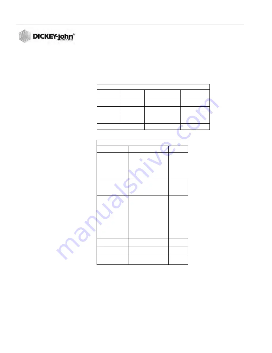
Table 3. COM1 Connector Pins Identification

Pin Number

Designation

Signal Name

Direction

1

AA

Protective Ground

NA

3

BB (RxD)

Received Data

To Device

6

CC (DSR)

Data Set Ready

To Device

7

AB

Signal Ground

NA

8

CF (RLSD)

Received Line

To Device

Signal Detector

11

Busy

To GAC 2100

20

CD (DTR)

Data Terminal Ready

To GAC 2100

Table 4. COM2 Programmable Options

Function

Option

Hex

Output Format

PRN 20
PRN 80
TST 20
PRN 81
CSV 01
 PRN 21

 Line Terminator

LF (Line Feed)

0A

CR (Carriage Return

0D

LF + CR

0A, 0D

CR + LF

0D, 0A

 Data Setup

300

 Baud Rate

600
1200
2400
4800
9600
19200

 Data Bits

7 or 8

 Parity

None, Even or Odd

 Stop Bits

1 or 2

Control MODE

Transmit Only
Auto Answer

 Control RTS

On (+)
 Auto

 Control DSR

Ignore
Active

Summary of Contents for gac 2100 agri

Page 1: ...GAC 2100 GRAIN ANALYSIS COMPUTER MODELS BLUE GRAY AND AGRI Operator s Manual SINCE 1966 ...

Page 2: ...ation 13 Display Screen 13 Adjust Screen Contrast 13 Keyboard Layout 13 Alarm 14 Key Functions 14 Menu Screens 15 Startup Procedure 17 Test Samples Quick Start 18 Measure Moisture 19 Basic Method 20 Grain Sample ID Numbers 22 Enter Numbers and Alpha Characters 22 ID Options 23 Factors Labels 23 Next Page View 24 Grain Selection 25 Select Grain Menu 25 Quick Keys 26 Calibrate Procedures 27 View Cal...

Page 3: ...ice Menu 8 Key 58 Quick Keys Menu 58 Test Weight Bias Adjustment 59 Test Weight Slope Adjustment 61 Moisture Bias Adjustment 62 Moisture Slope Adjustment 64 Test Unit Performance 67 Non Active Keys 67 View COM1 Port 2 Key 67 View COM2 Transmit Port 3 Key 68 View Display Characters 5 Key 69 View Diagnostic Mode 6 Key 70 Test Network Mode 7 Key 72 View Print Parameters 8 Key 73 Operator Maintenance ...

Page 4: ...lly hazardous situation which if not avoided could result in death or serious injury Use of the word CAUTION with the Safety Alert Symbol indicates a potentially hazardous situation which if not avoided may result in minor or moderate injury Use of the word CAUTION without the safety alert symbol indicates a potentially hazardous situation which if not avoided may result in equipment damage DISCLA...

Page 5: ...OPERATOR S MANUAL GAC 2100 Grain Analysis Computer Blue Gray Agri Models 11001 1688 201609 2 SAFETY NOTICES ...

Page 6: ...ated Test results calculate automatically to display the moisture content If enabled the temperature and approximate test weight density of the grain sample will display The product name grain calibration date and sample ID numbers display for identification purposes An additional screen of information includes readings for conductance D1 capacitance D2 weight D3 and temperature D4 values along wi...

Page 7: ...proper continual operation Error messages for out of limits moisture grain weight or grain temperatures Help screens to address operator issues Quick keys Blue model Test weight slope and bias adjustment all grains Moisture slope and bias adjustment all grains SPECIFICATIONS Supply Voltage and Frequency Limits 85 Vac to 264 Vac 48 440 Hz at 1 Amp Max Operating Temperature Range 2 C 35 6 F to 45 C ...

Page 8: ... Blue is capable of communicating with a computer via a direct connection using a null modem cable GAC 2100 AGRI and Gray The GAC 2100 AGRI and Gray models can output to a personal computer PC using the COM1 or COM2 ports The two communication ports are located on the rear of the unit and are identified as Printer Output Port COM1 and Computer Output Port COM2 Each must be properly configured to c...

Page 9: ...can print test data results The printout can include Facility name and address Current date and time Sample ID number Product name Grain calibration date Percent moisture Test Weight Grain temperature Unit serial number D1 through D4 values Data can automatically print at the end of each measurement cycle or manually initiated by pressing the Print key Print Key ...

Page 10: ... brace This brace supports the test cell whenever the unit is transported The position of the brace is controlled by a handle located on the rear panel behind the grain test cell Figure 5 A small spool is placed over the handle to prevent possible bumping and release of the handle during shipment To Disengage Shipping Brace 1 Remove spool and store with shipping materials 2 Push the handle in to u...

Page 11: ...ile attempting to lock the brace into the transport position Place the spool over the handle to prevent the accidental release of the shipping brace INSTRUMENT PLACEMENT Choose a clean environment that is protected from rapid changes in ambient temperature Avoid a hazardous classified location as defined in Article 500 of the NFPA Handbook of the National Electrical Code Instrument should be place...

Page 12: ...ully seated against the bottom panel This ensures minimum height above the counter top When moving the instrument to a different location re leveling may be required 3 After adjusting use a Phillips screwdriver in the center of the foot pad to hold the screw from turning and tighten the upper nut against the bottom panel of the unit 4 Ensure the lower nut remains tight against the foot pad Figure ...

Page 13: ...OPERATOR S MANUAL GAC 2100 Grain Analysis Computer Blue Gray Agri Models 11001 1688 201609 10 UNPACKING THE INSTRUMENT ...

Page 14: ...ive CONNECTING AC POWER 1 Verify that the ON OFF I O switch is in the OFF O position and that the shipping brace is in the OPERATE position 2 Plug the line cord into the connector on the rear panel next to the ON OFF switch 3 Plug the male end into an appropriate 3 wire grounded outlet The grounding pin on the line cord connects directly to the GAC 2100 frame When using an adapter with a grounding...

Page 15: ... grain sample drawer To Remove Sample Drawer Bottom 1 To remove the bottom of the grain sample drawer carefully lift the two plastic tabs at the front of the drawer Figure 7 2 Using a small screwdriver gently pry up on each tab and slide the bottom panel out the rear of the drawer Use care when prying on tabs to prevent breakage 3 When finished slide the grain drawer back into position This preven...

Page 16: ...ring light finger pressure to actuate each key Valid key closures result in short tone bursts while invalid keystrokes generate longer tone bursts The function of each key or key group is defined as follows and illustrated in Figure 8 Numbers 0 through 9 Decimal point and Minus keys All numeric keys perform dual functions making menu selections and entering numeric values The four numeric keys wit...

Page 17: ...r of screen i e PAGE 2 OF 8 Figure 9 Typical Screen Indicating More Pages PREVIOUS PAGE KEY Sequences backward through previously displayed pages Neither the Previous Page or Next Page keys roll over the pages to the beginning or end ENTER KEY Accepts the character string after an entry is complete LOAD KEY Initiates a grain cell loading sequence to begin a test cycle HELP KEY Provides context sen...

Page 18: ...YS Moves the cursor horizontally during alpha entries and certain functions during the SETUP mode UP AND DOWN KEYS Moves the cursor vertically during alpha entries and certain functions in the SETUP mode MENU SCREENS The Main menu displays once the start up checks are successfully completed The Main menu is the home screen that all other screens are accessed The Main menu displays five major selec...

Page 19: ...ODE 7 TEST NETWORK MODE 8 PARAMETERS MENU CALIBRATION MENU 1 VIEW CALIBRATION 2 ENTER CHANGE CALIBRATION 3 PRINT CALIBRATION LIST 4 OBTAIN CALIBRATION DATA 5 PRINT AUDIT MEMORY DATA SELECT ITEM NUMBER NEXT PAGE STATUS MORE PRESS LOAD TO BEGIN CORN 91051 ID 2 PAGE 8 OF 8 PAGE 7 OF 8 PAGE 6 OF 8 PAGE 5 OF 8 PAGE 4 OF 8 PAGE 3 OF 8 PAGE 2 OF 8 PAGE 1 OF 8 SELECT GRAIN 1 CORN 2 CORN HI MOIST 3 AMARANT...

Page 20: ...ON OFF I O switch is in the OFF O position and that the shipping brace is in the OPERATE position These are both located on the rear of the unit 1 Turn the power switch ON Initially a language screen appears showing eight choices Figure 12 Two English selections are available English US and English English US invokes parameters to display test weight for NTEP certified calibrations used in the Uni...

Page 21: ...n sample analysis consists of six basic steps 1 Select a grain for testing through keyboard entries 2 Pour grain sample into the hopper top of the unit and enter a sample ID number optional 3 Press the Load key The sample automatically loads drops the grain into the test cell and a strike off arm levels and removes the excess 4 Wait briefly for the test results to process The moisture reading and ...

Page 22: ...key 3 If a different grain is desired press the Previous Page key to return to the Main menu 4 Select the option SELECT GRAIN 2 key and choose a new grain refer to GRAIN SELECTION for additional information 5 Enter a sample ID number This number identifies the sample tested on the paper printout If the ENTER REQUIRED FOR ID is turned ON refer to CHOOSING ID OPTIONS in the ESTABLISHING PARAMETERS s...

Page 23: ... present to overfill the cell approx 0 5 liter or 2 cups Excess grain spills over the cell top and falls into the grain drawer below 2 If an ID number is not entered enter a number or skip to step 3 3 Press the Load key to begin the test cycle 4 GAC 2100 Blue If factors a type of label are enabled a screen displays the message ENTER RESULTS FOR THE FOLLOWING Disregard this screen by entering a num...

Page 24: ...tional information on the paper printout Up to four user defined factors or labels may display and print as specified on the Setup menu If this screen displays enter numbers as desired and select the Enter key If no factor names are specified the screen will not display 11 When the measurement is complete select the Unload key The test cell will invert dumping the grain and returning to the uprigh...

Page 25: ...for a moisture test When the PRESS LOAD TO BEGIN message appears stop and observe the screen The ID field on the lower left corner below the grain type appears and a small cursor will blink If necessary use the Down Arrow key to position the cursor next to the ID field ID _ Numbers are entered directly from the keypad and completed by selecting the Enter key 2 To enter letters select the Next Page...

Page 26: ...trument Setup ID numbers are added to each tested sample using one of three methods 1 Inserted Manually Any ID field including none at all are assigned to grain samples before each test This flexibility allows the creation of individualized numbering schemes 2 Automatic Sequencing Numbers can be sequentially assigned automatically to each moisture test For example 1 2 3 etc or specific letters i e...

Page 27: ...finition of each value is as follows D1 Conductance measurement to indicate grain surface moisture D2 Capacitance measurement to indicate internal grain moisture D3 Weight measurement to indicate grain weight D4 Temperature to indicate grain temperature Blue model Below the D calculations the TEST WEIGHT OFFSET as applicable appears This value is programmed on the Setup menu refer to Instrument Se...

Page 28: ...nique grain calibrations The first 40 are restricted and can only be changed by authorized personnel The remaining 24 are less secure and can be changed using the access code GAC 2100 AGRI Stores up to 8 different grain calibrations GAC 2100 Gray Stores up to 16 different grain calibrations To Select a Grain for Testing 1 Choose the Select Grain menu from the Main menu by selecting the 2 key Blue ...

Page 29: ...ins can be programmed for keyboard keys 1 2 and 3 The desired key grain changes the grain to be tested whenever the 1 2 or 3 key is pressed on the Press Load to Begin screen PAGE 8 OF 8 PAGE 7 OF 8 more PAGE 6 OF 8 more PAGE 5 OF 8 more PAGE 4 OF 8 more PAGE 3 OF 8 more PAGE 2 OF 8 more SELECT GRAIN 1 CORN 5 SOYBEANS 2 CORN HI MOIST 6 MILO 3 WHEAT HRW 7 BARLEY 4 AMARANTH 8 OATS PAGE 1 OF 8 more SE...

Page 30: ...lays the grain name moisture range calibration issue date and the nine calibration K values 4 If a printer is connected FACTORS Blue model are defined and AUTO RANGE is specified in the calibration this information also prints The lower right corner of the View Calibration screen indicates more meaning another page is available 5 Blue model Press the Next Page key to display the Factors screen The...

Page 31: ...ing the Access Code Changing calibrations is also possible through proper linking with a computer refer to the computer manual The same security code restrictions exist After gaining access changes to calibrations can be accomplished Figure 22 CALIBRATION MENU 1 VIEW CALIBRATION 2 ENTER CHANGE CALIBRATION 3 PRINT CALIBRATION LIST 4 OBTAIN CALIBRATION DATA 5 PRINT AUDIT MEMORY DATA SELECT ITEM NUMB...

Page 32: ...o enter a new calibration Select the appropriate key corresponding to the listing A screen displays TO PROCEED UNSEAL ACCESS PORT ON REAR PANEL and PRESS WHITE PUSHBUTTON Blue model If the grain selected is on one of the first five grain pages 5 x 8 40 changing the calibration is restricted to authorized personnel only Blue model If the grain selection is on pages 6 7 or 8 these calibrations can b...

Page 33: ...E function Press the Previous Page key to return to the Enter Change Calibration screen Note that the new grain title is now in place 5 Press the Enter key to accept the new grain title The cursor advances to the next position Issue Date 6 Enter the Calibration Issue Date up to 8 characters and select the Enter key The cursor returns to a flashing block in the ISSUE position The block signifies th...

Page 34: ...r K2 through K9 constants in the same manner as K1 11 Press the Enter key after entering each constant 4 digits 12 Press the Print key to print the calibration The present screen values print 13 Press the Next Page key to enter the Auto Range calibration selection The Auto Range screen allows entry for grains using higher or lower moisture levels than the current calibration These values are autom...

Page 35: ...e power switch ON and allow approximately thirty minutes to warm up before taking sample readings 2 Turn the printer ON 3 Verify the instrument is set up and functioning properly 4 From the Main menu choose the Calibration menu by pressing the 3 key 5 Press the 4 key and select OBTAIN CALIBRATION DATA 6 Enter a sample identification number so the sample is properly identified Key in a sample ID nu...

Page 36: ...MOIST 11 Run additional samples and record the actual moisture percentage for each sample 12 After running each sample press the Unload key CALIBRATION MENU 1 VIEW CALIBRATION 2 ENTER CHANGE CALIBRATION 3 PRINT CALIBRATION LIST 4 OBTAIN CALIBRATION DATA 5 PRINT AUDIT MEMORY DATA SELECT ITEM NUMBER NEXT PAGE STATUS PERFORMING SELF CHECKS PLEASE WAIT OBTAIN CALIBRATION DATA ID ENTER SAMPLE ID OBTAIN...

Page 37: ...omputer site Figure 27 For additional information concerning printing from the computer refer to the Communications Software manual included with the Communication software To Print the Audit Memory Contents 1 From the Main menu access the Calibration menu by selecting the 3 key Access PRINT AUDIT MEMORY DATA by selecting the 5 key A screen appears displaying PRESS PRINT TO BEGIN 2 Press the Print...

Page 38: ... DICKEY JOHN 40554 CURRENT DATE TIME 29 09 16 10 32 28 S N 1716 40554 EVENT COUNTER 1 DATE OF CHANGE 09 29 16 MM DD YY TIME OF CHANGE 10 33 25 HH MM SS LOG ON TIME 00 00 00 HH MM SS CHGCD 000000 PID TIME 10 34 00 HH MM SS CALIBRATION MENU 1 VIEW CALIBRATION 2 ENTER CHANGE CALIBRATION 3 PRINT CALIBRATION LIST 4 OBTAIN CALIBRATION DATA 5 PRINT AUDIT MEMORY DATA SELECT ITEM NUMBER NEXT PAGE STATUS PR...

Page 39: ...pond to keypad input and must be turned off and on to regain control and to resume normal grain measurement routines If any attempt is made to modify an auditable parameter the warning reappears and must be cleared again This limitation persists until the memory is cleared Figure 28 Audit Memory Full Screen PID Definition of Terms CB Calibration USRCD User Code OO D OTW Output Option Display Outpu...

Page 40: ...er 1 Press the 1 key Clear Audit Memory on the display 2 Locate the access port door located on the back of the instrument and remove seal if necessary from the door 3 Remove screw to open access port door 4 Press the white security button located on the bottom of the circuit board to advance to the next screen 5 When the white push button is pressed audit memory is cleared and the unit returns to...

Page 41: ...OPERATOR S MANUAL GAC 2100 Grain Analysis Computer Blue Gray Agri Models 11001 1688 201609 38 CALIBRATE PROCEDURES ...

Page 42: ... CODE 2 Enter the current personal access code or 0 and press the Enter key Enter 0 if the code has not been changed from factory settings MAIN MENU 1 MEASURE MOISTURE 3 CALIBRATION MENU 2 SELECT GRAIN 4 SETUP MENU 5 TESTS MENU SELECT ITEM NUMBER NEXT PAGE STATUS SETUP MENU 1 CLEAR COUNTER 2 ID OPTIONS 3 OUTPUT OPTIONS 4 EDIT ACCESS CODE SELECT ITEM NUMBER more 5 DATE TIME MENU 6 LABELS MENU 7 COM...

Page 43: ...turned OFF Enter Required for ID With each measurement a screen displays ENTER SAMPLE ID before the grain sample is measured This option ensures a grain sample identification number label is assigned for each test printout Optional Entry ID If both of the selections have been checked NO the ID number can be added to each measurement manually or not at all Manually added ID numbers do not require a...

Page 44: ...zed personnel through either the User ID Code from the computer site or as outlined below To Change the Output Options 1 From the Setup menu select OUTPUT OPTIONS 3 key A screen displays instructions on how to proceed Locating the Instrument Security Button 2 Locate the access port door located on the back of the instrument and remove seal if necessary from the door 3 Remove screw to open access p...

Page 45: ... of limit options selected below establish whether or not the enabled values appear on the display Eight separate settings are available for suppressing the enabled grain parameters OUTPUT OUT OF LIMITS RESULT If enabled three standard parameters are printed moisture grain temperature and approximate grain test weight Each measured parameter value appears next to its respective legend on the print...

Page 46: ...t display if weight is out of limits 8 WT Enabled readings display if weight and or temperature is out of limits but do not display if moisture is out of limits OUTPUT REPORT OF ALL ERRORS Enables all internal checked errors to print MOISTURE PRINT RESOLUTION Selects the resolution to either one tenth 0 1 percent or one hundredth 0 01 percent for moisture printout RADIX POINT Selects a decimal poi...

Page 47: ... seal on the rear panel of the unit and pressing the push button inside the access panel OUTPUT OPTIONS DISPLAY OUTPUT TEST WEIGHT YES DISPLAY OUTPUT TEMPERATURE YES DISPLAY OUT OF LIMITS RESULT YES OUTPUT OUT OF LIMITS RESULT YES SETUP MENU 1 CLEAR COUNTER 2 ID OPTIONS 3 OUTPUT OPTIONS 4 EDIT ACCESS CODE SELECT ITEM NUMBER more 5 DATE TIME MENU 6 LABELS MENU 7 COM MENU 8 SERVICE MENU OUTPUT OPTIO...

Page 48: ...de or 0 if set at factory code and press the Enter key The Edit Access Code screen displays a blank to be filled in The present access code appears to the right Figure 35 3 Enter the new access code Choose any numeric code of up to 4 digits 4 Enter the number and press the Enter key The new number must be used from this point forward to enter the access code level secured screens 5 Press Previous ...

Page 49: ...3 Enter the access code and select the Enter key The time displays based upon a 24 hour clock 4 Change the time by entering new numbers from the keyboard The time format is in hours minutes seconds HH MM SS Each unit is two digits and is separated by a decimal point For example to enter 3 32 59 P M enter 15 32 59 Use decimal points to separate units If accuracy is desired set the time slightly ahe...

Page 50: ...ous Page key to return Figure 37 Setting The Date To Change the Date Format 1 From the Date Time menu select the SET DATE FORMAT 3 key menu Figure 38 The screen displays ENTER ACCESS CODE 2 Enter the access code and press the Enter key The date format can be configured in one of three formats MM DD YY DD MM YY YY MM DD 3 Press the Left or Right Arrow keys 1 or 3 to select one of the three formats ...

Page 51: ... s name The user name can be two lines of up to 16 characters each TEXT STRINGS Blue model These are brief commonly used words or phrases added to the alpha screen for quick selection e g a name company etc when using alpha characters After programming each phrase is selected in the same manner as choosing a single character Up to ten text strings can be preset Each string is identified on the alp...

Page 52: ...he Backspace key as directed by the prompt on the bottom corner of the display The prompt disappears and is replaced with a cursor underline beneath the first character of the first line Blue model FACTORS e g customer id vehicle no load weight etc are assigned to individual grains For factor names Figure 41 the Select Grain To Enter Change menu appears and requests the selection of a grain name t...

Page 53: ...ny numeric key Press the Backspace key a second time and then select the Enter key The factor name should be blank 5 Enter the selected characters numbers to reflect the label Numbers and letters can be mixed by using the alpha screen 6 When completed press the Previous Page key to return to the Labels menu Figure 40 Edit Text Strings Blue Model LABELS MENU 1 EDIT USER NAME 2 EDIT TEXT STRINGS 3 E...

Page 54: ...ver The COM1 Data Communications Equipment port connector is located above the COM2 Data Terminal Equipment port connector The COM menu contains eight items with number 5 non active Selections 2 3 and 4 configure the COM1 port while 6 7 and 8 configure the COM2 port Each of the COM menu items is edited in a similar fashion LABELS MENU 1 EDIT USER NAME 2 EDIT TEXT STRINGS 3 EDIT FACTOR NAMES SELECT...

Page 55: ...ta setup COM1 or COM2 control lead setup Figure 42 Accessing the COM Menu To Configure COM PORT SELECT Press the 1 key on the Communications menu 1 After completing steps 1 through 4 from the basic entry procedure edit the configuration Four items appear on the menu for editing and configuring output information of both ports COM1 and COM2 Each item may be set to NONE COM1 COM2 or COM1 COM2 both p...

Page 56: ...T The configured port produces a printout of setup and test data by selecting the Print key 2 Once editing is complete select the Previous Page key to return to the Communications menu and for the next selection Figure 43 Accessing COM Port Select SELECT ITEM NUMBER NEXT PAGE STATUS ENTER ACCESS CODE __ COMMUNICATIONS PORT SELECTION AUTOMATIC RESULTS OUTPUT COM1 MANUAL RESULTS OUTPUT COM1 ERROR RE...

Page 57: ...e through six variations Select the appropriate format from the following six choices PRN20 Standard 20 column printer output PRN80 Standard 80 column printer output TST20 20 column test output of printer parameters PRN81 Standard 80 column printer output 2 lines CSV01 Comma separated variables PRN21 Special 20 column printer output PRN 20 format with the Grain Calibration Date Code Instrument Ser...

Page 58: ...cle the Baud Rate through seven choices 300 600 1200 2400 4800 9600 and 19200 bits second Choose the one that matches the rate of the equipment in use IMPORTANT COM2 data baud rate will always remain at 115200 Data Bits at 8 Parity None and Stop Bits at 1 even though the options to change are available in the menu The device connecting must change to match the instrument s baud rate SELECT ITEM NU...

Page 59: ...ferences are noted as applicable 1 After completing steps 1 through 4 from the basic entry procedure edit the configuration of the COM1 Port screen The COM1 DCE Control Lead Setup menu displays two lines refer to Accessing COM Control Lead Setup screens The busy line BUSY 11 notifies the GAC 2100 when the buffer in the printer computer is full and cannot accept more data The polarity of this line ...

Page 60: ...t the Previous Page key to return to the Communications menu for the next selection Figure 46 Accessing COM Control Lead Setup Screen SELECT ITEM NUMBER NEXT PAGE STATUS ENTER ACCESS CODE __ COM1 DCE CONTROL LEAD SETUP BUSY 11 IGNORE DTR 20 ACTIVE TO SELECT SETUP MENU 1 CLEAR COUNTER 2 ID OPTIONS 3 OUTPUT OPTIONS 4 EDIT ACCESS CODE 5 DATE TIME MENU 6 LABELS MENU 7 COM MENU 8 SERVICE MENU COMMUNICA...

Page 61: ...y 1 Select the 4 key Setup menu from the Main menu and then the Next Page key to access PAGE 2 of the Setup menu 2 Select the 1 key to choose the Quick Keys menu Three choices are available Figure 48 3 Select 1 2 or 3 to program as a Quick Key The Enter Access Code screen will appear 4 Enter the access code and select the Enter key The Program Quick Key screen will appear 5 Use the Left Right Arro...

Page 62: ...ss the 1 key AGRI and Gray models to choose TEST WEIGHT BIAS ADJUSTMENT Figure 49 3 Enter the access code and press the Enter key 4 Use the Left Right Arrow keys to select the grain type for correction The grain name and its number to the right change with each key SETUP MENU 1 CLEAR COUNTER 2 ID OPTIONS 3 OUTPUT OPTIONS 4 EDIT ACCESS CODE SELECT ITEM NUMBER more 5 DATE TIME MENU 6 LABELS MENU 7 C...

Page 63: ... value to indicate the number is recorded and a test weight bias has been applied 9 Press the Previous Page key to return to the Setup menu NOTE When a grain measurement is taken an asterisk appears in front of the test weight value to indicate a test weight bias is enabled Figure 49 Setting The Test Weight Adjustment 1 3 5 0 SETUP MENU 1 CLEAR COUNTER 2 ID OPTIONS 3 OUTPUT OPTIONS 4 EDIT ACCESS C...

Page 64: ...plays 5 Use the Left Right Arrow keys to select the grain type for correction The grain name and its number to the right change with each key stroke Advance until the correct grain displays If the end of the list is reached the list will wrap around to the beginning and start again 6 When the correct grain is found press the Enter key The Test Weight Adjustment screen displays the selected grain v...

Page 65: ... of the Setup menu 2 Press the 4 key Blue or press the 3 key AGRI and Gray models to select MOISTURE BIAS ADJUSTMENT Proceeding screens are locked until manually pressing the security button located on the circuit board inside the instrument SETUP MENU 1 CLEAR COUNTER 2 ID OPTIONS 3 OUTPUT OPTIONS 4 EDIT ACCESS CODE SELECT ITEM NUMBER more 5 DATE TIME MENU 6 LABELS MENU 7 COM MENU 8 SERVICE MENU S...

Page 66: ... the list will wrap around to the beginning and start again 7 When the correct grain is found press the Enter key The adjustment screen displays the selected grain values The adjustment consists of 3 numerical settings consisting of whole number tenths and hundredths values 8 Press the Left Right Arrow keys to select the desired digit to change 9 Change the selected value using the Up Down Arrow k...

Page 67: ...y button located on the circuit board inside the instrument Locating the Instrument Security Button 3 Locate the access port door located on the back of the instrument and remove seal if necessary from the door SETUP MENU 1 CLEAR COUNTER 2 ID OPTIONS 3 OUTPUT OPTIONS 4 EDIT ACCESS CODE SELECT ITEM NUMBER more 5 DATE TIME MENU 6 LABELS MENU 7 COM MENU 8 SERVICE MENU SETUP MENU 1 QUICK KEYS MENU 2 T...

Page 68: ...nges on the MOISTURE SLOPE line with each button press 10 When finished press the Enter key to accept the final bias value An asterisk appears next to the value to indicate the number is recorded and a moisture slope bias is applied 11 Press the Previous Page key to return to the Setup menu Figure 53 Slope Bias Adjustment 1 3 5 0 SETUP MENU 1 CLEAR COUNTER 2 ID OPTIONS 3 OUTPUT OPTIONS 4 EDIT ACCE...

Page 69: ...OPERATOR S MANUAL GAC 2100 Grain Analysis Computer Blue Gray Agri Models 11001 1688 201609 66 INSTRUMENT SETUP ...

Page 70: ...ep Figure 54 Entering The Tests Menu VIEW COM1 PORT 2 KEY The COM1 Test screen displays the configuration of the COM1 communications port Values are set from the SETUP MODE to match the driving device i e printer of the port To Access the COM1 Port 1 Access the COM1 Menu by selecting the 2 key on the Tests menu Figure 55 The COM1 Test screen displays the COM1 serial data setup status Baud Rate Dat...

Page 71: ...Y is indicated Press the Print key to produce a printout of the character set through the COM2 port Press the Previous Page key to return to the Tests menu NOTE COM2 data setup protocols are fixed at Baud Rate 115200 Data Bits at 8 Parity at None and Stop Bits at 1 although the settings menu may show other values Figure 56 Entering the COM2 Transmit Test Menu TESTS MENU 1 non active 2 COM1 3 COM2 ...

Page 72: ...en shows characters symbols and digits that can display by the unit 2 After viewing select the Previous Page key to return to the Tests Menu Figure 57 Display Mode Screen TESTS MENU 1 non active 2 COM1 3 COM2 TRANSMIT 4 non active SELECT ITEM NUMBER NEXT PAGE STATUS 5 DISPLAY 6 DIAGNOSTIC MODE 7 TEST NETWORK MODE 8 PARAMETERS MENU 0 1 2 3 4 5 6 7 8 9 ABCDEFGHIJKLMNOPQRSTUVWXYZ _ a b c d e f g h i ...

Page 73: ...ounts from weight oscillator 4 Ce f Ratio of empty cell weight oscillator counts to full cell weight oscillator counts When the 4 key is selected item 3 blanks to recalculate The message PLEASE WAIT followed by PLACE WEIGHT ON CELL THEN PRESS ENTER displays A test weight is placed on top of the test cell and then the Enter key is selected After a short wait the results will display 5 SCD1 D1 condu...

Page 74: ...of screen 5 Vc Voltage of 2 MHz oscillator 6 Vc Vn Voltage of 2 MHz oscillator minus null voltage 7 Vsc Voltage of 2 MHz oscillator with on board test network engaged 8 Vsc Vn Voltage of 2 MHz oscillator with on board test network engaged minus null voltage 4 When finished press the Previous Page key twice to return to the Tests menu Figure 59 Diagnostic Mode Printout of Page 1 Figure 60 Diagnosti...

Page 75: ...reen 2 Press the Load key to start the measuring cycle When the test is complete the results display and print automatically if a printer is connected Figure 62 Figure 61 Displaying Test Network Mode Results TESTS MENU 1 non active 2 COM1 3 COM2 TRANSMIT 4 non active SELECT ITEM NUMBER NEXT PAGE STATUS 5 DISPLAY 6 DIAGNOSTIC MODE 7 TEST NETWORK MODE 8 PARAMETERS MENU PERFORMING SELF CHECKS PLEASE ...

Page 76: ...mory To View the Parameters Menu 1 At the Main menu press the 5 key 1 Press the 8 key from the Tests menu and press the Parameters menu This menu displays the unit parameters 2 To print the values shown on the screen select any menu followed by the Print key A printout of all the screens results Figure 64 Item 6 also prints all stored errors 3 When finished viewing the screens select the Previous ...

Page 77: ... 4 VIEW CAC TWCC 5 VIEW SERIAL NUMBER 6 VIEW FACTORY MODES SELECT TEST NUMBER NEXT PAGE STATUS VIEW FACTORY MODES BURN IN MODE OFF ERROR STORING ON ERRORS HAVE BEEN STORED VIEW SERIAL NUMBER S N 1716 23601 VIEW CAC TWCC CALIB ADJ CONSTANT 0 9870 TWCC 0 9870 VIEW WEIGHT CONSTANTS POINT WEIGHT RATIO 1 0 000 1 00000 2 61 500 1 02754 3 120 400 1 05453 4 181 800 1 08340 5 240 600 1 11179 6 300 300 1 14...

Page 78: ... Printout 05 18 16 09 59 59 S N 1716 23601 REF TEMP 25 00 REF VOLT 1 1560 EC COUNT 40399 WEIGHT TABLE 1 0 000 1 00000 2 61 500 1 02754 3 120 400 1 05453 4 181 800 1 08340 5 240 600 1 11179 6 300 300 1 14108 CAC 1 0000 IC 1122 BURN IN MODE OFF ERROR STORING ON CURRENT ERRORS ERROR 2 05 04 16 18 42 2 05 17 16 16 50 4 5 50134 SELECT TEST NUMBER ...

Page 79: ...OPERATOR S MANUAL GAC 2100 Grain Analysis Computer Blue Gray Agri Models 11001 1688 201609 76 TEST UNIT PERFORMANCE ...

Page 80: ...wer Reach inside and very carefully clean the strike off arm spring Before performing step 5 ensure that all fingers or other foreign objects are not in cell area 5 Press the Unload key The cell will rotate 180 degrees to dump the residue from the cell cleaning procedure The hopper doors will close 6 Press the Previous Page key twice to return to the Main menu FUSE REPLACEMENT 1 Disconnect the lin...

Page 81: ...t a DICKEY john representative for assistance 6 The moisture reading exceeds the upper limit Select a new grain and retry 7 The moisture reading exceeds the lower limit Select a new grain and retry 8 The empty cell ambient temperature has exceeded its limit Allow the GAC 2100 to reach normal operating temperature 9 The sample temperature exceeds its limit Allow the sample to either cool down or wa...

Page 82: ...lly connected to frame Received Data pin 3 Transmitted data from the GAC 2100 Data Set Ready pin 6 ON positive voltage whenever the GAC 2100 is powered Signal Ground pin 7 Common reference for all other COM1 signals Received Line Signal Detector pin 8 ON positive voltage whenever the GAC 2100 is powered Busy pin 11 Gates the transmission of data from the GAC 2100 The COM1 Control Lead Setup screen...

Page 83: ...GNMENT DETAILS COM2 refer to Table 5 is configured as Data Terminal Equipment DTE Protective Ground pin 1 Electrically connected to frame Transmitted Data pin 2 Data is transmitted from this pin Received Data pin 3 Data is received on this pin Table 3 COM1 Connector Pins Identification Pin Number Designation Signal Name Direction 1 AA Protective Ground NA 3 BB RxD Received Data To Device 6 CC DSR ...

Page 84: ...p screen configures this line as active or ignored If configured as ACTIVE an OFF condition negative or zero voltage inhibits the transmission of data from the GAC 2100 Results display but are not buffered for output on COM2 If not connected this line should be configured as IGNORED Signal Ground pin 7 Common ground reference for all other COM2 signals Received Line Signal Detector pin 8 Currently...

Page 85: ...OPERATOR S MANUAL GAC 2100 Grain Analysis Computer Blue Gray Agri Models 11001 1688 201609 82 APPENDIX A COMMUNICATION PORTS ...

Page 86: ...cial damages Said part will not be considered defective if it substantially fulfills the performance expectations THE FOREGOING WARRANTY IS EXCLUSIVE AND IN LIEU OF ALL OTHER WARRANTIES OF MERCHANTABILITY FITNESS FOR PURPOSE AND OF ANY OTHER TYPE WHETHER EXPRESS OR IMPLIED DICKEY john neither assumes nor authorizes anyone to assume for it any other obligation or liability in connection with said p...

Page 87: ...tion 11001 1688 201609 Operator s Manual 5200 Dickey john Road Auburn IL 62615 www dickey john com 217 438 3371 217 438 6012 fax 2016 DICKEY john Corporation DICKEY john Sales 800 637 2952 agsales dickey john com DICKEY john Technical Support 800 637 3302 service dickey john com Europe Sales and Technical Support 33 1 41 19 21 80 europe dickey john com ANALYSIS COMPUTER ...

Reviews: