


DLEV1
Operating Instructions
- 17 -
5.3.3 Control
Pilot (CP) State (Vehicle Simulation)
•
With the CP State rotary switch selector various vehicle states
can be simulated when the test adaptor is connected to the
charging station.
•
Vehicle states are simulated with different resistances
connected between CP and PE conductors.
•
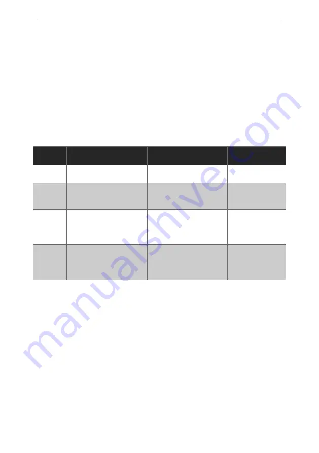
Correlation between resistance and vehicle is shown in Table
below:
Correlation between resistance and current capability
of the charging cable
Vehicle
State
Description
Resistance between
CP & PE
Voltage at CP
Output (1kHz)
A
Electric vehicle (EV)
not connected
Open
∞
± 12V
B
Electric vehicle (EV)
connected & not
ready to charge
2.74
kΩ
± 9V/-12V
C
Electric vehicle (EV)
connected, non-
vented & ready to
charge
882
Ω
± 6V/-12V
D
Electric vehicle (EV)
connected,
ventilation required &
ready to charge
246
Ω
± 3V/-12V
5.3.4 CP Output Signal Terminals
•
CP output terminals are connected to CP and PE conductors of
the tested charging station via the test cable, the green socket
is connected to PE.
•
This output is intended for the connection of an oscilloscope to
check the waveform and amplitude of the CP signal.
•
Control Pilot function uses Pulse Width Modulation [PWM].
•
The purpose of the Control Pilot function is communication
between a vehicle and the charging station, the duty cycle of the
PWM signal defines the possible available charging current.
•
For details of communication protocol please refer to IEC/EN
62851-1& IEC/HD 60364-7-722 and the documentation of the
manufacturer of the charging station.