background image

10

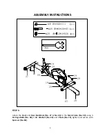
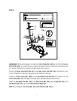
IMPORTANT:

Boltul de prindere de pe partea stanga si dreapta (45 si

40) trebuie sa fie penetreze conectorul (47) si suportul.

Aceasta va asigura stabilitatea si durabilitatea aparatului

fitness.

Pentru a monta boltul de prindere, tineti-l perfect drept

astfel incat boltul sa treaca prin bratele pedaliere si prin

tija ghidonului. Daca boltul de prindere este conectat pe

tija ghidonului la un unghi, atat boltul cat si tija pot fi

deteriorate.

Summary of Contents for 3435E

Page 1: ...MANUAL DE UTILIZARE DHS 3435E IMPORTANT VA RUGAM SA CITITI CU ATENTIE ACEST MANUAL INAINTE DE A FOLOSI APARATUL PASTRATI ACEST MANUAL PENTRU REFERINTA VIITOARE...

Page 2: ...ala sau greata In acest caz trebuie sa consultati doctorul inainte de a va continua antrenamentul 4 Nu lasati copiii sau animalele in preajma aparatului Acest aparat a fost creat pentru a fi folosit d...

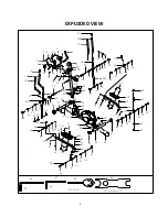
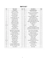
Page 3: ...45 47 46 49 50 31 32 33 33 37 38 20 21 24 23 22 21 52A 53 29 25R 11 60 60 41 60 61 30 36 21 60 60 70 39 39 32 33 33 35 25L 41 41 60 61 48 49 46 46 70 40 17 63 41 44 62 56 63 34 16 62 43L 43R 55 55 64...

Page 4: ...10 Fire superioare senzor 1 40 Bolt de prindere dreapta 16 89 23 1 2 S8 1 11 Surub 12 11 3 1 41 Dop J40 25 15 4 12 Protectie maner 26 5 510 2 42 Capac clema 1 13L R Ghidon St Dr 2 43L R Pedale St Dr 2...

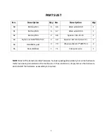
Page 5: ...Dop 50 61 50 2 55 Suport pedale St Dr 2 27 Bara stabilizatoare fata 1 56 Saiba d10 20 2 0 4 28 Bolt de transport M8 60 20 H5 4 57 Fire reglaj tensiune 1 29 Saiba arc d8 20 2 R30 8 58 Fire inferioare...

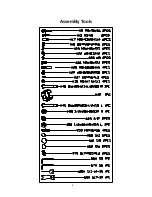
Page 6: ...5 Piese si unelte...

Page 7: ...19 M8 H16 S13 4pcs 27 28 28 65 19 29 19 29 59 29 19 PASUL 1 Asamblati bara stabilizatoare fata 27 si bara stabilizatoare spate 65 pe cadrul principal 59 folosind 4 bolturi de transport 28 4 saibe arc...

Page 8: ...zistenta aceasta va asigura cablului de tensiune lungimea necesara pentru a fi conectat Conectati firele superioare senzor 10 cu firele inferioare senzor 58 conform celor indicate mai sus in Fig 1 Asi...

Page 9: ...ele arc 29 PASUL 3 Fixati Tija ghidon St Dr 25L 25R pe suportul ghidon 64 folosind 2 bolturi 24 2 saibe arc 23 si 2 saibe 22 strangeti si fixati folosind cheia franceza 68 Acoperiti ambele capete ale...

Page 10: ...ntine filetare inversa Cand asamblati partea stanga boltul de prindere de pe partea stanga 45 trebuie sa fie rotit in sens contrar acelor de ceasornic pentru a fi strans METODA ALTERNATIVA DE ASAMBLAR...

Page 11: ...rtul Aceasta va asigura stabilitatea si durabilitatea aparatului fitness Pentru a monta boltul de prindere tineti l perfect drept astfel incat boltul sa treaca prin bratele pedaliere si prin tija ghid...

Page 12: ...L 43R pe suportul pedalelor 55 folosind 4 bolturi 17 4 saibe 37 si 4 piulite nylon 38 strangeti si fixati folosind cheia franceza 68 Acum puteti strange suruburile 53 si saibele arc 29 pe suportul ghi...

Page 13: ...2PCS 13L 13R 18 17 19 18 25L 25R 19 17 PASUL 5 Introduceti ghidonul stang si drept 13L R pe capatul de sus a tijei ghidonului stang si drept 25L si 25R Fixati folosind 2 Bolturi 17 2 saibe arc 18 si 2...

Page 14: ...losind cheia Inbus S6 67 apoi acoperiti clema folosind capacul 42 Conectati firele superioare senzor 10 la firele computerului 71 Apoi folosind 2 suruburi 15 montati computerul 1 pe suportul computeru...

Page 15: ...ea urmatoare 2 TIMP TIME Memoreaz automat timpul antrenamentului pana la 99 59 MIN 3 VITEZA SPEED Afiseaza viteza curenta de la 00 00 pana la 999 9 KM H sau MPH 4 DISTANTA DISTANCE Calculeaza distanta...

Page 16: ...onsola va afisa doar statistica dorita Pentru a selecta MODUL DE BLOCARE apasati butonul MODE cand cursorul este pe functia pe care doriti sa o selectati 4 BATTERII REZOLVAREA PROBLEMELOR Acest monito...

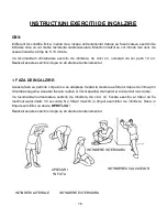
Page 17: ...ntrenamentul 1 FAZA DE INCALZIRE Aceasta faza va permite corpului sa se adapteze treptat la cresterea efortului depus de inima prin circulatia sanguina Aceasta faza va reduce si riscul aparitiei cramp...

Page 18: ...aproximativ 5 minute Apoi repetati faza de incalzire prin reluarea exercitiilor de intindere si aveti grija sa nu va fortati muschii printr o intindere Pe masura ce va creste rezistenta va fi necesar...

Page 19: ...USER S MANUAL IMPORTANT Please read this manual carefully before using the product Retain owner s manual for future reference...

Page 20: ...ildren and pets away from the equipment The equipment is designed for adult use only 4 Use the equipment on a solid flat level surface with a protective cover for your floor or carpet To ensure safety...

Page 21: ...46 49 50 31 32 33 33 37 38 20 21 24 23 22 21 52A 53 29 25R 11 60 60 41 60 61 30 36 21 60 60 70 39 39 32 33 33 35 25L 41 41 60 61 48 49 46 46 70 40 17 63 41 44 62 56 63 34 16 62 43L 43R 55 55 64 54 54...

Page 22: ...l 2 14 End cap 28 32 50 2 44 Bolt M10 50 13 S17 2 15 Screw M5 10 2 45 Hinge bolt L 16 89 23 1 2 S8 1 16 Bushing 32 25 L83 2 46 Alloy bushing 28 4 24 12 16 1 4 17 Bolt M8 40 20 S14 Grade A 6 47 Link co...

Page 23: ...remove the hardware and reinstall the hardware as assembly is required No Description Qty No Description Qty 60 Ball cap S13 6 66 Allen wrench S8 1 61 Ball cap S18 6 67 Allen wrench S6 1 62 Ball cap...

Page 24: ...5 Assembly Tools...

Page 25: ...20 2 R30 4pcs 19 M8 H16 S13 4pcs 27 28 28 65 19 29 19 29 59 29 19 STEP 1 Attach the Front and Rear Stabilizers No 27 No 65 to the Main Frame No 59 using 4 Carriage Bolts No 28 4 Arc Washers No 29 and...

Page 26: ...red to connect it Connect the Upper Sensor Wire No 10 to the Lower Sensor Wire No 58 shown above in Fig 1 Ensure that the connection is properly secured before continuing Lower the Tension Cable No 52...

Page 27: ...Main Frame No 59 using Hinge Bolt L No 45 1 Wave Washer No 70 1 Spring Washer No 49 and Nylon Nut L No 50 Tighten and secure with Allen Wrench S8 No 66 and Spanner No 69 Repeat this process to complet...

Page 28: ...assembling the left side you must screw counter clockwise to tighten Connect the Spring Washers No 49 Nylon Nut L No 50 and Nylon Nut R No 48 and attach the Ball Caps No 61 You can now reattach the L...

Page 29: ...R to the Connecting Rods No 55 using 4 Bolts No 17 4 Washers No 37 and 4 Nylon Nuts No 38 tighten and secure with Spanner No 68 You may now securely tighten the Screws No 53 and Arc Washers No 29 on H...

Page 30: ...8 H16 S13 2PCS 13L 13R 18 17 19 18 25L 25R 19 17 Insert the left and right Handlebars No 13L R into the tops of left and right Swing Rods No 25L and No 25R Fix using 2 Bolts No 17 2 Arc Washers No 18...

Page 31: ...23 tighten with Allen Wrench S6 No 67 then cover the clamp using Clamp Cover No 42 Connect the Upper Sensor Wire No 10 to the Computer Wire No 71 Then using 2 Screws No 15 attach the Computer No 1 to...

Page 32: ...ES The rate of calories burned per hour 0 0 999 9 KCAL 6 PULSE Displays the detected heart rate in beats per minute 40 240 BPM To measure your heart rate place the palm of your hands on both contact p...

Page 33: ...the stretching exercises as shown below Each stretch should be held for approximately 30 seconds do not force or jerk your muscles into a stretch If it hurts STOP 2 THE COOL DOWN PHASE This stage is t...

Reviews: