7
STEP 2:
64
29
29
53
53
29
53
10
52B
57
58
S6
#53 M8*16*S6 4PCS
#29 d8* 20*2*R30 4PCS
10
58
57
52B
59
52A
#67
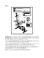
IMPORTANT: Before attempting to connect the Tension Cable (No. 52B) ensure that the Tension
Control (No. 52A) is turned all the way to the left (the lowest level of resistance), this will provide
the tension cable with the necessary length required to connect it.
Connect the Upper Sensor Wire (No. 10) to the Lower Sensor Wire (No. 58), shown above in Fig.
1. Ensure that the connection is properly secured before continuing.
Lower the Tension Cable (No. 52B) from the Handlebar Post (No. 64) and connect it to the
Tension Wire (No. 57), following the tension cable assembly shown above in Fig. 2.
Attach the Handlebar Post (No. 64) to the Main Frame (No. 59) using 4 Screws (No. 53) and 4
Arc Washers (No. 29), secure with Allen Wrench S6 (No. 67).
NOTE: Do not tighten the Screws (No. 53) and Arc Washers (No. 29) yet.
FIG. 1
FIG. 2
Summary of Contents for 3435E
Page 6: ...5 Piese si unelte...
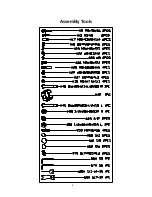
Page 24: ...5 Assembly Tools...


