background image

NDS3107C Multiplexer User Manual 

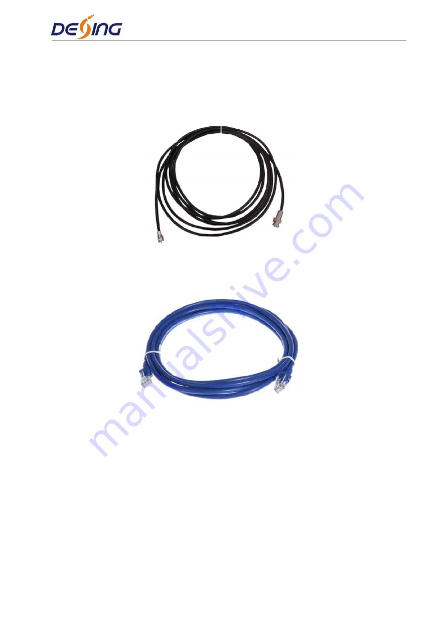
User can find ASI output port on the device according to connector mark described in the rear 

panel illustration, and then connect the ASI cable (in the accessories); one end is connected to the 

Multiplexer’s ASI output port and the other end to the Modulator’s ASI input port or ASI input 

of other equipment. Multiplexer’s ASI cable illustrated as follows: 


2.4.2 Network cable (Category 5) illustration:   


Summary of Contents for FiberLabs NDS3107C

Page 1: ...NDS3107C Multiplexer User s Manual Dexin Digital Technology Corp Ltd...

Page 2: ...1 5 APPEARANCE AND DESCRIPTION 2 CHAPTER 2 INSTALLATION GUIDE 4 2 1 ACQUISITION CHECK 4 2 2 INSTALLATION PREPARATION 4 2 3 WIRE S CONNECTION 6 2 4 SIGNAL CABLE CONNECTION 6 CHAPTER 3 OPERATION 8 3 1...

Page 3: ...EN300 468 standard Support 8 ASI input for re multiplexing Support 512 IP input through DATA 1 and DATA 2 over UDP protocol Support accurate PCR adjusting PID re mapping PSI SI rebuilding and editing...

Page 4: ...General Power supply AC 110V 10 50 60Hz Or AC 220V 10 50 60Hz 1 4 Principle Chart 1 5 Appearance and Description Front panel Illustration 1 2 3 4 5 6 Indicator area All the indicators will light on w...

Page 5: ...Rear panel Illustration 3 7 8 9 10 11 12 7 ASI IN1 8 TS input ASI OUT 1 TS output ASI OUT 2 TS output as mirror of ASI 1 ASI OUT 3 TS output 8 ASI OUT 4 TS output as mirror of ASI 3 9 NMS Ethernet Por...

Page 6: ...The details of installation will be described at the rest part of this chapter Users can also refer rear panel chart during the installation The main content of this chapter includes Checking the poss...

Page 7: ...check before running 2 2 3 Grounding Requirement All function modules good grounding is the basis of reliability and stability of devices Also they are the most important guarantee of lightning arrest...

Page 8: ...ed to protective ground it should adopt independent way say share the same ground with other devices When the device adopts united way the grounding resistance should be smaller than 1 Caution Before...

Page 9: ...in the rear panel illustration and then connect the ASI cable in the accessories one end is connected to the Multiplexer s ASI output port and the other end to the Modulator s ASI input port or ASI in...

Page 10: ...er or paging up down when parameter is inactivated LOCK Locking the screen canceling the lock state After pressing lock key the system will question the users to save present setting or not If not the...

Page 11: ...d total bit rate in the first row while the 8 channels respective serial number input real time encoding bit rate in the second row in turn It shows as below Dexin MUX3107C P1 55 999Mbps P2 55 999Mbps...

Page 12: ...e it shows the No warning Alarm status No warning Up time Press Enter to enter Up time and it displays the working time duration of the device It times upon power on Uptime 00 37 54 up 3 3 2 TS Config...

Page 13: ...3 2 DATA2 3 1 1 Output Protocol 3 1 2 MPTS1 3 1 3 MPTS2 3 1 1 1 Output Mode 3 1 1 2 Filter Null PKT 3 1 1 3 Reset IP Address 3 1 1 4 Destination Port 3 3 4 Network Setting After enter Network Setting...

Page 14: ...iguration Restore Configuration YES NO Factory Set Choose yes to restore the device into factory s default configuration 12 Reset Web Login Password Choose yes to reset the web login password Version...

Page 15: ...e PC Personal Computer and the device with net cable and use ping command to confirm they are on the same network segment I G the PC IP address is 192 168 99 252 we then change the device IP to 192 16...

Page 16: ...ut channel TS indicators Green light indicates the TS is normal which otherwise turns to red Figure 2 Input From the menu on left side of the webpage clicking Input it displays the interface where use...

Page 17: ...oid disturbing with the device scrambling function To enable disable the PID remapping To refresh the input program information To refresh the output program information Select one input program first...

Page 18: ...the interface where users can configure the output TS Figure 6 Output channel select Click this button to effect the configurations at last Figure 6 Function IP Output NDS3107C supports TS output in I...

Page 19: ...displays the interface as Figure 8 where to set NMS and DATA port parameters Figure 8 System Upgrade Clicking upgrade it displays the screen as Figure 9 where to update the device by using the update...

Page 20: ...System Password Clicking Password it displays the screen as Figure 10 where to set the login account and password for the web NMS Figure 10 System Log Clicking Log it displays the screen as Figure 11...

Page 21: ...User Manual Figure 11 Save Load From the menu on left side of the webpage clicking Save Load it displays the screen as Figure 12 where to save restore factory setting Remove backup load your configur...

Page 22: ...0 to 45 C Making sure good ventilation for the heat sink on the rear panel and other heat sink bores if necessary Checking the input AC within the power supply working range and the connection is corr...

Page 23: ...NDS3107C Multiplexer User Manual 21 Chapter 6 Packing list NDS3107C Multiplexer 1pcs User Manual 1pcs ASI Cable 8pcs Power Cord 1pcs...

Reviews: