background image


Getting Started Guide


Sales Office:


+1 (301) 975-1000


Technical Support:


+1 (301) 975-1007


E-mail:


[email protected]


WWW:


www.patton.com


Part Number: 


07M1195-GS, Rev. A


Revised: 


February 12, 2009


Start Installation

For Quick 


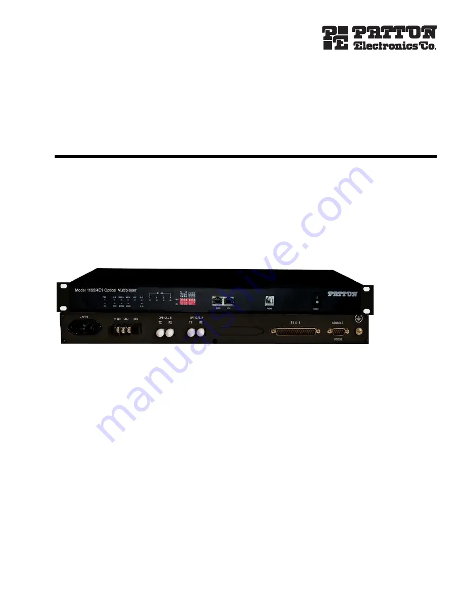
Model 1195/4E1 
Optical Multiplexer

Summary of Contents for 1195/4E1

Page 1: ...ales Office 1 301 975 1000 Technical Support 1 301 975 1007 E mail support patton com WWW www patton com Part Number 07M1195 GS Rev A Revised February 12 2009 Start Installation For Quick Model 1195 4...

Page 2: ...and will at our option repair or replace the product should it fail within one year from the first date of the shipment This warranty is limited to defects in workmanship or materials and does not cov...

Page 3: ...l information 13 2 Applications overview 21 3 Model 1195 4E1 installation 23 4 Connecting the RS 232 port 29 5 CLI configuration 34 6 GUI configuration 47 7 Contacting Patton for assistance 66 A Speci...

Page 4: ...s 28 Connecting Ethernet Links 28 Verifying the connection 28 Definition for Ethernet Interfaces 28 4 Connecting the RS 232 port 29 Connecting the RS 232 port 30 RS 232 port cable details 31 RS 232 pi...

Page 5: ...the status of ethernet port 44 Clear the performance statics log of Ethernet E1 GFP 44 Add a telnet user 45 Delete a Telnet user 45 Check the list of Telnet users 45 View the status of remote system p...

Page 6: ...67 Alternate Patton support for Europe Middle East and Africa EMEA 67 Warranty Service and Returned Merchandise Authorizations RMAs 67 Warranty coverage 67 Out of warranty service 68 Returns for cred...

Page 7: ...7 Model 1195 Getting Started Guide Table of Contents Physical 73 B Connector pinouts 74 DB 37 connector pinout Model 1195 4E1 75 DB 37 connector pinout details for E1 connections 75...

Page 8: ...ndow 49 11 Add Remove System 50 12 Select COM port 51 13 Select TCP IP address 51 14 Login 52 15 Add user 52 16 Status Monitoring 53 17 System Monitoring 54 18 System settings 55 19 E1 settings 56 20...

Page 9: ...ypical application Chapter 3 on page 23 provides hardware installation procedures Chapter 4 on page 29 provides information for connecting the RS 232 port Chapter 5 on page 34 provides information for...

Page 10: ...n to important information The alert symbol and CAUTION heading indicate a potential haz ard Strictly follow the instructions to avoid property damage The shock hazard symbol and CAUTION heading indic...

Page 11: ...ered units ensure that the power cable used meets all applica ble standards for the country in which it is to be installed and that it is con nected to a wall outlet which has earth ground Hazardous n...

Page 12: ...t Futura bold italic type Parts of commands which are related to elements already named by the user are in boldface italic font Italicized Futura type Variables for which you supply values are in ital...

Page 13: ...13 Chapter 1 General information Chapter contents Model 1195 14 Features and Benefits 14 Front View 15 Rear View 20...

Page 14: ...power detection RPD Low power consumption Orderwire EOW channel for end to end installation and maintenance Local and remote loop back test for diagnostics 1 1 Fiber Path protection ALS Auto Laser Shu...

Page 15: ...4 RPD RPD WORKB WORKB NOPB NOPB WORKA WORKA NOPA NOPA MANG OFF ON POWER I O ETH PHONE LOOP 4 LOOP 3 LOOP 2 LOOP 1 PWR PWR CV CV E 6 E 6 E1 LOS 1 2 3 4 1 1 ON OFF CV_CLR MUTE MASK ALS_EN 2 2 3 3 4 4 LO...

Page 16: ...ical B is not working NOPA Red ON Optical signal loss is detected on port A Blinking ALS is enabled on the remote device OFF No loss NOPB Red ON Optical signal loss is detected on port B Blinking ALS...

Page 17: ...l loss happened at the corresponding tributary OFF No loss 1 1 ON OFF R CV_CL MUTE MASK ALS_EN 2 2 3 3 4 4 ALM LOF E1 LOS E 3 1 2 3 4 RPD WORKB NOPB WORKA NOPA MANG OFF ON POWER I O ETH PHONE LOOP 4 L...

Page 18: ...ion alarms will be trig gered if a new event of E1 signal loss occurs even if MASK is ON ALS_EN ON Enable ALS function OFF Disable ALS function ON Enable remote loopback of E1 OFF Disable remote loopb...

Page 19: ...ough 3 PHONE Phone Interface RJ 11 Cable Standard 2 wire cable 64 Kbps PCM coding 4 POWER Power Switch ON Power ON OFF Power OFF Front View 19 Model 1195 Getting Started Guide 1 General information 1...

Page 20: ...tion Rear View DC 48 V E1 4 1 II 220 V PGND GND 48V OPTICAL B TX RX OPTICAL A TX RX RS232 CONSOLE 220 V PGND GND 48V OPTICAL B TX RX OPTICAL A TX RX E1 4 1 II RS232 CONSOLE Optical Interfaces Console...

Page 21: ...21 Chapter 2 Applications overview Chapter contents Typical Model 1195 Application 22...

Page 22: ...l 1195 Application 22 Model 1195 Getting Started Guide 2 Applications overview Typical Model 1195 Application Figure 8 shows the typical application for the 1195 model Figure 8 Typical application for...

Page 23: ...wer 24 Grounding 25 Connecting the optical interface 26 Connecting the DB 37 connector 27 Connecting E1 links 28 Definition for E1 Interfaces 28 Connecting Ethernet Links 28 Verifying the connection 2...

Page 24: ...mains cable provided to the system The polarity should not be reversed while connecting Otherwise you can get your system damaged AC Power To connect the AC 220V power DC Power To connect the DC 48V...

Page 25: ...used with the AC 220V power supply the 3 core socket must be grounded for protec tion The other equipment e g optical terminal connected with this equipment must also be grounded To connect the Earth...

Page 26: ...than 10 km optical attentuators must be intalled on the Optical Links Otherwise the optics will be permanently damaged WARNING DC 48 V E1 4 1 II 220 V PGND GND 48V OPTICAL B TX RX OPTICAL A TX RX RS23...

Page 27: ...necting the DB 37 connector Note See Appendix B on page 74 for DB 37 connector pinouts DC 48 V E1 4 1 II 220 V PGND GND 48V OPTICAL B TX RX OPTICAL A TX RX RS232 CONSOLE DB 37 Female Connector 4xE1 Si...

Page 28: ...Ethernet port of the equipment at both sides as well as the Ethernet Ports of the devices that are connected to the equipment Connect the Ethernet links Please ensure that the connecting LANs on both...

Page 29: ...29 Chapter 4 Connecting the RS 232 port Chapter contents Connecting the RS 232 port 30 RS 232 port cable details 31 RS 232 pin definition 31 Configuring HyperTerminal 32...

Page 30: ...t DC 48 V E1 4 1 II 220 V PGND GND 48V OPTICAL B TX RX OPTICAL A TX RX RS232 CONSOLE DB9 Connector Female DB9 Connector Male DB9 Female Connector DB9 Male Connector PC Note RS232 COM Port cable is pro...

Page 31: ...er 24 AWG Length 3 meters Connections As per details given below DB 9 Pin Number Definition RS 232 2 RS 232 input signal for management 3 RS 232 output signal for management 5 GND Others NC Connecting...

Page 32: ...C 2 Select Programs Accesories Communications HyperTerminal The following screen will be dis played 3 Enter a name for the new connection and click OK The connection window will be displayed Configuri...

Page 33: ...uld be 6 Click Apply then click OK 7 A new HyperTerminal session screen will display Press Enter The system prompt will appear on the screen This prompt is generated by the system Now you may access c...

Page 34: ...her the E1 Port is looped back 40 Check the alarms of E1 Tributary 41 Configure laser port receive mode 41 View the current status of laser port 42 Reset the system 42 Set configure the default settin...

Page 35: ...alarm View the alarms of E1 tributary setcvmode Configure the receive mode of the laser port showlaser View the current status of the laser port reset Perform a hot restart setdefault Configure the se...

Page 36: ...195 help cmdname enter 1195 sete1loop FORMAT sete1loop E1ID Local_Loop Remote_Loop EXPLAIN Enable Disable the loopback of E1 port use this command to put the E1 line into loop back mode or non loop ba...

Page 37: ...d Response Notes 1195 showip enter System IP Address 192 168 0 155 Shows the IP address of the local device Command Response Notes 1195 showmask enter System Subnet Mask 255 255 255 0 Shows the subnet...

Page 38: ...s 1195 setsnmpset string enter System SNMP set community string Configure the SET community of SNMP of the local device where string 0 to 31 Command Response Notes 1195 setip ipaddr enter System IP ad...

Page 39: ...dress macaddr Change the MAC of the local device where macaddr any valid MAC address Note A new MAC address will be activated after a system reset Command Response Notes 1195 showsysinfo enter View th...

Page 40: ..._loop remote_loop enter E1ID 0 8 0 All 1 8 E1ID Local_Loop 0 1 loop status 0 non loop 1 loop Remote_Loop 0 1 loop status 0 non loop 1 loop Enable Disable the loopback of E1 port Use this command to pu...

Page 41: ...butary Configure laser port receive mode Command Response Notes 1195 e1alarm enter Shows the alarms of E1 tributary See example below Shows the alarms of E1 tributary Command Response Notes 1195 setrc...

Page 42: ...laser interface Include alarm status the config of receive mode the current work inter face Command Response Notes 1195 reset enter Performs a hot restart Performs a hot restart Command Response Note...

Page 43: ...t AN rate duplex flow enter Port A AN B Rate C Duplex D Flow E Configure the Ethernet port perfor mance parameters where A 1 Ethernet Port No B 0 AN not done 1 AN done C 0 10Mbit s 1 100Mbit s D 0 hal...

Page 44: ...mmand Response Notes 1195 ethperform enter View the performance of Ethernet View the performance of Ethernet Command Response Notes 1195 ethstatus enter View the status of Ethernet View the status of...

Page 45: ...eluser Username Password enter SUCCESS TO DELETE TELNET USER Deletes a telnet user where user name any valid username and pass word any valid password Command Response Notes 1195 showuser enter TELNET...

Page 46: ...of E1 s CV alarm Command Response Notes 1195 settonemask A enter enable disable diable 0 enable 1 Configure the status of alarm tone mask where A 0 1 disable 0 enable 1 Command Response Notes 1195 sho...

Page 47: ...atus Monitoring 53 System Monitoring 54 Start stop monitoring 54 Configure view alarms 54 Change the Trap Community and or Port 54 View log 55 Managing Trap Details 55 Configuring System Settings 55 C...

Page 48: ...will automatically start and display the main window Figure 9 CD flash screen 2 Click on Graphical User Interface GUI to begin the installation The Install Wizard window will dis play 3 Click Next to...

Page 49: ...on between the equipment and a PC or to establish a remote login to the equipment It also allows the user to configure the system as desired and also provides the information about the status of the s...

Page 50: ...m make a local connection through the COM port then click on Set tings IP Settings Removing a system There are two ways to remove a system Option 1 In the Add Remove System window select the system th...

Page 51: ...reen and select TCP COM Single System Figure 12 Select COM port 2 From the drop down menu select the COM port that is in use The message COM X is selected will display 3 Click OK To access the system...

Page 52: ...ase sensitive Adding Removing Users Adding a user To add a new user click on Option at the top of the screen and select Add User A window will display Click New Enter information for all of the fields...

Page 53: ...view the status and current alarms of the 1195 click on Tributary Interface at the top of the screen and select Status Monitoring Figure 16 Status Monitoring If a status is Red there is an alarm If t...

Page 54: ...olor of the system s button indicates the status of alarms for the system Red indi cates that there are alarms present on the system Green indicates that there are currently no alarms found on the sys...

Page 55: ...on at the top of the screen and select Multisystem Monitoring NMS The list of systems will display 1 Select the duration of traps from Trap View drop down list box at the bottom of the screen 2 Click...

Page 56: ...ttings at the top of the screen and select E1 Set tings A window will display where you can make the desired changes Figure 19 E1 settings Configuring IP Settings To configure settings for IP addresse...

Page 57: ...ystem Configuring Trap Settings To configure the settings for receiving traps click on SNMP at the top of the screen and select Trap Settings A window will display where you can create a list of monit...

Page 58: ...ult Settings To restore the default settings click on Set Default at the top of the screen A window will display Click Yes to begin the process Figure 22 Default settings The default settings are For...

Page 59: ...iguration SNMP Community To set and view the SNMP Set and SNMP Get Community options click on SNMP at the top of the screen and select SNMP Community A window will display Figure 23 SNMP Community Not...

Page 60: ...ng Settings To view general system settings click on Show Settings at the top of the screen A window will display that shows current system values Click on any of the properties displayed in the list...

Page 61: ...will display Click Open and select the path where you want to save the backup file Click Save Figure 25 Back up Restore To restore settings from the backup file click on File at the top of the screen...

Page 62: ...of synchronization is to update the database with the current set tings in the system For example if you make any changes to system settings through the CLI Figure 27 Synchronize Report List of syste...

Page 63: ...e list of traps click on File at the top of the screen and select Report List of Traps A screen will display To view the traps of a specific system click on Traps of Selected System To view traps of a...

Page 64: ...tting Started Guide 6 GUI configuration Read Me To learn about system requirements for running the GUI click on Help at the top of the screen and select Read Me The instructions will display in a wind...

Page 65: ...To learn about firmware and GUI release versions click on Help at the top of the screen and select About A window will display with the system information Figure 31 View system information Exiting th...

Page 66: ...n support headquarters in the USA 67 Alternate Patton support for Europe Middle East and Africa EMEA 67 Warranty Service and Returned Merchandise Authorizations RMAs 67 Warranty coverage 67 Out of war...

Page 67: ...x 1 253 663 5693 Alternate Patton support for Europe Middle East and Africa EMEA Online support available at www patton inalp com E mail support e mail sent to support patton inalp com will be answere...

Page 68: ...ll be issued upon receipt and inspection of the equipment 30 to 60 days We will add a 20 restocking charge crediting your account with 80 of the purchase price Over 60 days Products will be accepted f...

Page 69: ...e 71 Transmitter Optical Characteristics 71 Receiver Optical Characteristics 71 Optical Interface Specifications 1550nm Single Mode 71 Transmitter Optical Characteristics 71 Receiver Optical Character...

Page 70: ...G 823 compliant Connectors Male DB37 interface with RJ 45 connectors 120 balanced or Male DB37 interface with BNC coaxial connectors 75 unbalanced Optical Type of Transmitter Class 1 Laser Transmitte...

Page 71: ...1195 Getting Started Guide A Specifications Optical Interface Specifications 1310nm Single Mode Transmitter Optical Characteristics Receiver Optical Characteristics Optical Interface Specifications 15...

Page 72: ...uto sensing Compliance Ethernet Version 2 0 IEEE802 3 10Base T 100Base TX Activity Full half duplex Interface Rate 100 Mbps Ethernet data transmission rate Connector RJ 45 Configuration Management and...

Page 73: ...tting Started Guide A Specifications Environment Temperature 5 C 55 C for operation 40 C to 70 C for storage Humidity 5 to 95 35 C non condensing Physical Width 1552 mm Depth 434 mm Height 44 mm Weigh...

Page 74: ...74 Appendix B Connector pinouts Chapter contents DB 37 connector pinout Model 1195 75 DB 37 connector pinout details for E1 connections 75...

Page 75: ...37 connector pinout Model 1195 75 Model 1195 Getting Started Guide B Connector pinouts DB 37 connector pinout Model 1195 Figure 32 DB 37 connector pinout DB 37 connector pinout details for E1 connecti...

Reviews: