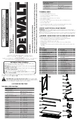


Tools Required for Rack Assembly:
4 mm Hex Key (included) OR 4 mm Hex Bit (included); Rubber
Mallet (not included), Flat-Head Screwdriver (not included)
20
21
22
24
23
25
27
29
28
30
31
26
33
32
READ ALL INSTRUCTIONS
• Read all instructions thoroughly.
• Remove all components from the box, and lay them on the floor in an orderly fashion.
• Wear eye protection.
• Be cautious of sharp edges.
• Keep this information for further reference.
• If you are not stacking a second rack at this time, then please store the Stacking Plates for potential
future use as they will be needed.
WARNING:
Serious or fatal crushing injuries can occur from rack tipping over. To prevent this, the
assembled rack must always be secured to a wall, especially in earthquake-prone environments, where
surfaces are uneven, and where children and/or pets are present.
NOTE:
For ease of assembly, two (2) vertical beams feature pre-bolted horizontal and diagonal beams, as
well as pre-attached U-bracket covers.
1. Place one (1) vertical beam and one (1) pre-bolted vertical beam on the floor, parallel to one another
(about 18"/45.7 cm apart). The widest part of the teardrop-shaped hole pattern on each beam should
be facing upward (or away from you). (Fig. 1)
2. There are two versions of the U-bracket covers - an “A” side and a “B” side. Before moving forward,
cover the U-shaped brackets on the vertical beam with the covers by mirroring the covers on the pre-
bolted vertical assembly.
3. Insert the free end of the diagonal beam into the free end of the horizontal beam. Align the holes, and
insert both beams into the U-shaped bracket at the top of the opposing vertical beam. Use the included
hex key or drill bit to thread the vertical assembly bolt through the holes and into the weld nut attached
to the U-shaped bracket. Do not fully tighten the bolt yet. (Fig. 2)
4. Swing out the bottom horizontal beam, and insert it into the U-shaped bracket at the bottom of the
opposing vertical beam. Thread a vertical Assembly bolt through the holes and into the weld nut. Do not
fully tighten the bolt. (Fig. 2)
5. Repeat Steps 1-4 to assemble the three remaining upright frames. Once all are assembled, fully tighten
the bolts on all four corners. Be careful not to over-tighten the bolts; there should be no deformation of
the U-shaped brackets and/or horizontal beams.
Expandable Upright Frame Instructions (Fig. 1-2)
BEFORE YOU BEGIN:
*Horizontal Work Station
*Vertical Work Station
FIG. 1
FIG. 2
(61 cm)
2 ft
TOP HORIZONTAL BEAM
BOTTOM HORIZONTAL BEAM
DIAGONAL
BEAM
18"
(45.7 CM)
NOTE:
It is recommended for one person to hold the upright frames in place while a second person installs
the crossbeams.
1. There is a set of locking tabs at both ends of every crossbeam. To begin assembly, take one crossbeam
and insert the tabs into two of the holes on the lower portion of one upright frame. Engage the locking
tabs into the holes using a downward motion. The locking pin hole should be at the top. Make sure the
end of the crossbeam is flush against the upright frame. (Fig. 3)
2. Repeat for the opposite side of the upright frame. Tap the ends of the crossbeam closest to the upright
frames with a rubber mallet until fully seated. The crossbeam and locking tabs should easily slip into
place. If they do not, then recheck the alignment of the teardrop-shaped holes and tabs. Too much
force may damage the interlock between the crossbeam and upright frame. (Fig. 4)
3. Using the methods listed above, install another crossbeam to the opposite side of the upright frames,
parallel to the first crossbeam you installed. Make sure both crossbeams are at the same level.
4. Repeat the previous steps for installing crossbeams spaced four slots from the top of the rack
upright frames. (Fig. 5)
Part 1: Crossbeam Installation (Fig. 3-5)
LOWER HALF OF WORK STATION (2 PARTS)
FIG. 3
FIG. 4
FIG. 5
LOCKING
PIN HOLE
NOTE:
This fold up drawer is designed to be placed under a shelf so that the shelf may act as the drawer top.
1. Open the fold up drawer and install the drawer pull by slipping it into the tabs on the inside of the fold
up drawer front. Secure it using the provided drawer carriage bolt and nut in the top corners of the fold
up drawer. Make sure the nuts are inside of the fold up drawer. (Fig. 6)
2. Using the remaining drawer carriage bolts and nuts, secure the top corners of the fold up drawer on the
opposite side of the drawer pull. (Fig. 7)
3.
NOTE:
Ensure that the drawer slides open to the front of the rack.
Install the mounting brackets with the drawer slides onto the rack with six slots spaced from the top
of the vertical beams. This will be directly underneath the top set of crossbeams that were installed
previously. This is done by positioning the mounting bracket with drawer slides on the inside edge of
the rack uprights. Slide down the mounting bracket with drawer slides to seat them properly. Make
sure both brackets are level with one another before proceeding. Then, the hardware on the mounting
brackets can be tightened. (Fig. 8)
4.
NOTE:
Ensure mounting brackets with drawer slides are level before installing the fold up drawer.
Have a helper assist with the install of the fold up drawer onto the drawer slides.
Slide the guides on the fold up drawer into the rails on the mounting bracket: there should be a distinct
click when the guides have seated properly. (Fig. 8)
5. To secure the brackets to the rack’s uprights, install the locking pins into the mounting bracket with
drawer slides. (Fig. 9)
Part 2: Drawer Assembly (Fig. 6-9)
FIG. 6
FIG. 7
FIG. 8
REAR OF
DRAWER
DRAWER
PULL


