background image

7

A

B

D

FIG. 1

C

1

0

E

G

F

I

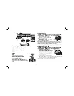
Components (Fig. 1)

  A.  Spindle Lock 

F.  Backing flange

 B. Wheel 

G. Clamp nut

 C. Guard 

H. Side handle

  D.  Carbon Brush Door 

I.  Wrench

 E. Switch

Features

SWITCH

The tool is controlled by the switch (E).

ASSEMBLY AND ADJUSTMENTS

Attaching the Side Handle 

FIG. 2

H

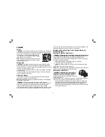
The side handle (H) can be fitted to either

side of the gear case in the threaded holes, as shown. 

Before using the tool, check that the handle is tightened 

securely. 

Rotating the Gear Case 

WARNING: To reduce the risk of serious personal injury, turn off and unplug 

tool be fore making any adjustments or removing or in stall ing ac ces sories.  

  1.  Remove guard and flanges from tool. 

90

˚

90

˚

  2.  Remove the four corner screws attaching
the gear case to motor housing.
  3.  Separating the gear case from motor housing 

not more than 6.4mm, rotate

the gear case head to desired position

NOTE:

 If the gear case and motor housing become separated by more than 6.4 mm, 

the tool must be serviced and re-assembled by a D

E

WALT service center. Failure to 

have the tool serviced may cause brush, motor and bearing failure. 
  4.  Re-install screws to attach the gear case to the motor housing. Tighten screws 

to 18 in./lbs. torque. Overtightening could cause screws to strip.

Mounting and Removing Guard

WARNING: To reduce the risk of serious personal injury, turn off and unplug 

tool be fore making any adjustments or removing or in stall ing ac ces sories. 

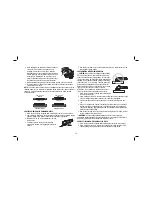
  1.  Loosen screw. Push the guard down                

FIG. 2

I

J

C

until the guard lug (I) engages and rotates freely 

in the groove (J) on the gear case hub.

  2.  Rotate guard (C) into desired working position. 

The guard body should be positioned between 

the spindle and the operator to provide maxi-

mum operator protection.

  3.  Tighten the screw to secure the guard on the 

gear case cover. Fasten torque no less than 2 Nm. You should be unable to rotate 

the guard by hand. Do not operate grinder with a loose guard.

To remove the guard, loosen screw and pull up on the guard.

Summary of Contents for D28000-XE

Page 1: ...D28000 XE Heavy Duty Small Angle Grinder INSTRUCTION MANUAL ...

Page 2: ......

Page 3: ...ces such as pipes radiators ranges and refrigerators There is an increased risk of electric shock if your body is earthed or grounded c Do not expose power tools to rain or wet conditions Water entering a power tool will increase the risk of electric shock d Do not abuse the cord Never use the cord for carrying pulling or unplugging the power tool Keep cord away from heat oil sharp edges or moving...

Page 4: ...te the power tool Power tools are dangerous in the hands of untrained users e Maintain power tools Check for misalignment or binding of moving parts breakage of parts and any other condition that may affect the power tool s operation If damaged have the power tool repaired before use Many accidents are caused by poorly maintained power tools f Keep cutting tools sharp and clean Properly maintained...

Page 5: ...ated speed of the accessory must be at least equal to the maximum speed marked on the power tool Accessories running faster than their rated speed can break and fly apart e The outside diameter and the thickness of your accessory must be within the capacity rating of your power tool Incorrectly sized accessories cannot be adequately guarded or controlled f The arbour size of wheels flanges backing...

Page 6: ... lose control the cord may be cut or snagged and your hand or arm may be pulled into the spinning accessory l Never lay the power tool down until the accessory has come to a complete stop The spinning accessory may grab the surface and pull the power tool out of your control m Do not run the power tool while carrying it at your side Accidental contact with the spinning accessory could snag your cl...

Page 7: ...ond the sanding pad presents a laceration hazard and may cause snagging tearing of the disc or kickback Safety Warnings Specific for Wire Brushing Operations a Be aware that wire bristles are thrown by the brush even during ordinary operation Do not overstress the wires by applying excessive load to the brush The wire bristles can easily penetrate light clothing and or skin b If the use of a guard...

Page 8: ...and cement and other masonry products and arsenic and chromium from chemically treated lumber CCA Your risk from these exposures varies depending on how often you do this type of work To reduce your exposure to these chemicals work in a well ventilated area and work with approved safety equipment such as those dust masks that are specially designed to filter out microscopic particles Avoid prolong...

Page 9: ...nd motor housing become separated by more than 6 4 mm the tool must be serviced and re assembled by a DEWALT service center Failure to have the tool serviced may cause brush motor and bearing failure 4 Re install screws to attach the gear case to the motor housing Tighten screws to 18 in lbs torque Overtightening could cause screws to strip Mounting and Removing Guard WARNING To reduce the risk of...

Page 10: ...ory must have a 16 mm arbor hole If it does not it may have been designed for a circular saw and should not be used Use only the accessories shown on manual Accessory ratings must be above listed minimum wheel speed as shown on tool nameplate Mounting and Using Depressed Center Grinding Wheels and Sanding Flap Discs MOUNTING AND REMOVING HUBBED WHEELS WARNING To reduce the risk of serious personal...

Page 11: ...els Type 27 guard 100 mm 4 wire wheel Type 27 guard 75 mm 3 wire cup brush Type 1 guard backing flange abrasive cutting wheel clamp nut Cutting Wheels Type 1 guard backing flange diamond cutting wheel clamp nut threaded clamp nut 100 mm Sanding Flap Discs Type 27 guard backing flange non hubbed sanding flap disc ...

Page 12: ...ls used for cutting and edge grinding may break if they bend or twist while the tool is being used to do cut off work or deep grinding To reduce the risk of serious injury limit the use of these wheels with a standard Type 27 guard to shallow cutting and notching less than 13 mm 1 2 in depth The open side of the guard must be positioned away from the operator For deeper cutting with a Type 1 cut o...

Page 13: ...be used for removing rust scale and paint and for smoothing irregular surfaces 1 Allow tool to reach full speed before touching tool to work surface 2 Apply minimum pressure to work surface to allow the tool to operate at high speed 3 Maintain a 5 to 10 angle between the tool and work surface for wire cup brushes 4 Maintain contact between the edge of the wheel and the work surface with wire wheel...

Page 14: ...k surface 2 Apply minimum pressure to work surface allowing tool to operate at high speed The cutting rate is greatest when the tool operates at high speeds 3 Once a cut is begun and a notch is established n the workpiece do not change the angle of the cut Maintain the angle of the cutting wheel to the work surface This will keep you from bending the wheel which could result in wheel breakage and ...

Page 15: ... with your sales receipt within 30 days for a replacement unit or a full refund Reverse above procedures to finish brush change WARNING Make sure all screws are correctly fitted and tightened before re connecting the tool to power supply Cleaning WARNING Blowing dust and grit out of the motor housing using clean dry compressed air is a necessary regular maintenance procedure Dust and grit containi...

Page 16: ... 654 155 or NZ 0800 339258 for a free replacement D28000 XE ANGLE GRINDER WARNING To reduce the risk of injury user must read instruction manual Always use proper eye and respiratory protection DEWALT Industrial Tool Co Baltimore MD 21286 U S A For Service Information Call 1 800 654155 www DEWALT com au ...

Page 17: ...15 ...

Page 18: ...16 ...

Page 19: ...17 ...

Page 20: ...d APR10 Part No N039392 D28000 XE Copyright 2009 2010 DEWALT The following are trademarks for one or more DEWALT power tools the yellow and black color scheme the D shaped air intake grill the array of pyramids on the handgrip the kit box configuration and the array of lozenge shaped humps on the surface of the tool ...

Reviews: