background image


HDS9336 


  Caution


  Danger


Preparation Before Installation


●During  transportation,  handling,  and installation  of  switchboard  equipment,  avoid  collisions 
between the switchgear equipment and doors, walls, shelves, etc. 

●When the equipment is unpacked and transported, it is strictly forbidden to put it down and 
drag it gently to avoid damage to the switchboard equipment. 

●Do  not  place  the  switcher  equipment  in  a  flammable,  explosive  atmosphere  or  smoke 
environment. Do not perform any operation in this environment. 

●Operating  equipment  should  be  kept  away  from  water  and  moisture.  The  water  in  the 
switchgear or moisture will cause damage to the circuit of the switchgear equipment. 

●A certain amount of heat will be generated during the operation of the switcher. Ensure that 
the switchgear equipment is ventilated and the switcher device can operate normally. 


●It is a fatal hazard that indirect contact with the power supply by wet objects is prohibited. 
Unregulated, incorrect high-voltage operation can cause accidents such as fire or electric shock. 

●It is forbidden to install and remove the switchgear equipment and power cord. When the power 
cord is in contact with the conductor, an arc or spark may be generated, which may result in fire 

or electric shock.


Summary of Contents for HDS9326

Page 1: ...6 CH SWITCHER HDS9336 VER 1 0 Users Manual ...

Page 2: ...nt should be kept away from water and moisture The water in the switchgear or moisture will cause damage to the circuit of the switchgear equipment A certain amount of heat will be generated during the operation of the switcher Ensure that the switchgear equipment is ventilated and the switcher device can operate normally It is a fatal hazard that indirect contact with the power supply by wet obje...

Page 3: ...3 Parameter 09 4 Control Panel and Interface 10 4 1 Control Panel 10 4 1 1 Area Description 10 4 1 2 Key Description 11 4 1 2 1 Functional area 11 4 1 2 2 Audio Control Area 12 4 1 2 3 Transition control area 15 4 1 2 4 Integrated control area 16 4 1 2 5 PGM PVW Selection 18 5 Stream instructions 22 6 System menu settings 26 7 Failure and Maintenance 29 8 More switcher options 30 ...

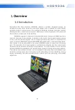
Page 4: ...ls can be output synchronously which is convenient for users to expand HDS9336 supports SDI HDMI embedded audio external analog audio After mixing it can be embedded in the output SDI HDMI signal or output from the analog port The resolution of all input signals is automatically adapted and the output signal resolution can be selected according to requirements It is quite flexible The six channel ...

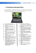
Page 5: ...DMI 1xSDI Support 1 channel SDI output custom PGM PVW Support MIX FADE WIPE switching effects support CUT hard cutting AUTO automatic switching and FTB emergency switching the switching rate can be set Support PIP function sub window size and position can be adjusted arbitrarily border thickness and color can be set Adjustable transition rate Support Tally interface to connect to the call system B...

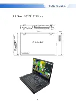
Page 6: ...6 HDS9336 2 1 Size 362 215 43mm ...

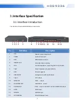
Page 7: ...LLY Direct broadcast call system DB 15 7 RJ45 Network upgrade 8 LINE IN OUT Analog stereo audio input output 9 Type C UVC output 10 HDMI OUT PGM output 11 MULTIVIEW OUT MULTIVIEW output 12 SDI PGM OUT PGM output SDI OUT2 custom PGM PVW output 13 SDI IN 4xSDI input 14 HDMI IN 2xHDMI input 15 DC POWER IN DC12V 5A power input 3 Interface Specification 3 1 Interface Introduction The interface of Devic...

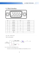
Page 8: ...2 PGM IN2 7 PVW IN2 13 PGM IN3 8 PVW IN3 14 PGM IN4 9 PVW IN4 15 PGM IN5 10 PVW IN5 3 PGM IN6 4 PVW IN6 5 GND Note PIN1 PIN2 not used TALLY Online schematic Note Tally LED for external display devices Tally output Active low Tally LED is lit High level is invalid Tally out is off ...

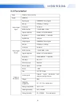
Page 9: ... SDI HDMI Video Signal Bit rate 270Mbps 10 2Gbps Connector Standard Reflection loss 15dB 5MHz 3GHz Signal amplitude 800mV 10 SDI HDMI Impedance 100Ω HDMI 75 Ω SDI DC offset 0V 0 5V Clock recovery Optional Common Parameters Power supply 12V DC Power 20W Size 362 215 43mm Control panel Support on site production and integrate multiple buttons Weight 2KG Operating temperature 0 50 No condensation Sto...

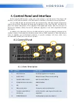
Page 10: ...In addition to the innovation of the case the HD switcher has also been completely optimized for the interface connector Environmentally friendly materials with new RoHS standards are More demanding in terms of durability and environmental protection to provide customers with more stable more environmentally friendly more cost effective products 4 1 Control Panel NO Name Description 1 Functional a...

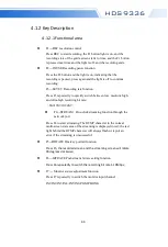
Page 11: ...it rate 6M 12M 18 24M F4 STREAM One click streaming function through the network port Press F4 to start streaming The RTMP character in the normal multi screen state area of the streaming is displayed in red the red light behind the RTMP character will always flash or report an error if the streaming is unsuccessful F5 ROTATE One key portrait function Press F5 the recorded screen and the streaming...

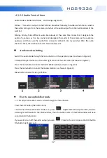
Page 12: ... output from the live broadcast of the switcher Mixing Mixing three different audio live outputs at the same time means that I designate the audio of a camera as the live sound and designate the audio of the camera as the audience applause and then I use the audio from a mixer to embed it into my switcher After the audio channel is fixed the video channel can be switched at will How to use audio f...

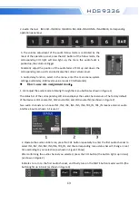
Page 13: ... selection as shown in Figure 1 Show After confirming the audio channel you selected press the CH1 button the button lights up in blue as shown in Figure 2 Indicates to turn on the first audio channel and finally turn on the MUTE button master switch the button lights up in blue as shown in Figure 3 Adjust the volume of the first channel of audio At this time the audio output from the PGM live bro...

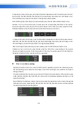
Page 14: ...election as shown in the figure below Shown After confirming the audio channel you have selected press the ON button the button is on Indicates to turn on the third audio channel press the VOL VOL corresponding to the second channel to adjust the volume of the third audio At this time the audio output from the PGM live broadcast is fixed to the first second and Three way audio How to use listen au...

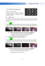
Page 15: ...ight after pressing then click the CUT button or use the T Bar or AUTO to switch The effect diagram is as follows MIX transition effects superimpose and gradually superimpose the B picture on the A picture until the end of the transition the picture is completely replaced by the B picture FADE in and fade out transition effects Click FADE in the special effect control area it will show a green lig...

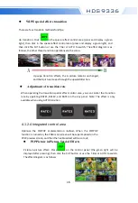
Page 16: ...control area press and display a green light then click in the special effect control area press and display a green light and then click the CUT button or use the T bar or AUTO to switch The effect diagram is as follows the other three transition operations are the same Adjustment of transition rate When operating the transition special effect control area you can control the transition rate by o...

Page 17: ...etting You can choose small medium large settings Border switch setting You can choose the on off setting Border width setting The border width can be selected from 2 7 thickness borders and the value will increase decrease by 1 every time you turn the knob Border color setting You can choose white red green green to set the border color PIP size and position POP Picture out picture effects Pictur...

Page 18: ... from 2 7 thickness borders and the value will increase decrease by 1 every time you turn the knob Border color setting You can choose white red green green to set the border color POP size and position 4 1 2 5 PGM and PVW Introduction of multiview output window Freeze screen function The STILL button is defined as the screen freeze function Press the button to turn on the green light to turn on t...

Page 19: ...ectively corresponding to buttons 1 6 on the switcher control panel As shown below PGM and PVW output signal After the device is connected to the video signal source press 1 PGM and 2 PVW in the button panel and the live and preview signal sources in the output multi screen monitor are 1 PGM and 2 PVW respectively the signal sources are SDI IN1 and SDI IN2 respectively The effect diagram is as fol...

Page 20: ... live PGM signal source 1 6 can be switched freely with the preview PVW signal source The effect diagram is as follows PGM and PVW source switching After pressing the button in the button panel the screen will output color bars Luma Key Turning on this function will deduct the black part of the key source Then overlap with the background image to achieve the purpose of keying and superimposing the...

Page 21: ...he current luma key information as shown in the figure below KEY KEY Luma BKGD Green Level 0 64 Exit Under the menu you can set the key source select the video source press the menu and then adjust various parameters through the menu Chroma KEY Chroma key keying supports dynamic video source image and static source keying Switching the opportunity to key out the blue or green part of the key sourc...

Page 22: ...l 0 64 Exit The video source item can select the key source the KEY type has chroma key_green and chroma key_blue and the level setting range is 0 64 5 Stream instructions 1 HDS9336 is a hardware streaming device which needs to be connected to the LAN through the STREAM interface on the side of the device then enter the streaming settings in the device menu there is a Stream ip corresponding to th...

Page 23: ...the browser and enter the IP address in the push streaming setting menu of our device For example in the following figure we fill in the automatically obtained 192 168 1 233 IP address into the browser to search and then enter the WEB interface ...

Page 24: ...s that each group of push addresses can be named by themselves and the naming is only valid for letters and numbers in the stream setting in the menu you can see the stream name you saved on the WEB interface The streaming address is the streaming address of the live streaming platform and the settings need to be saved after filling in you can view the name of the streaming platform you saved in t...

Page 25: ...he interface If you can t remember the IP address of the WEB interface for a long time you can check the WEB interface IP address in the menu push settings 6 To change the IP address and streaming settings you need to save the settings under the parameter setting module 7 The index in the stream settings can save 8 groups of streams the user name only displays English characters and numbers and th...

Page 26: ...utput and switch through the knob The audio mode corresponds to the selection of mixing and following which can be selected through the knob The output resolution is the PGM output of the corresponding device which can be switched by the knob 1080I50 60 and 1080P24 25 30 50 60 In the power on default state press the knob to enter the main menu as shown in the figure below Status CH1 SRC SDI1 CH2 S...

Page 27: ...obtaining an IP address One is dynamic configuration and the other is a static IP address that needs to be manually configured Remember to save and exit after the setup is complete Note When setting the device IP address do not repeat the IP address to avoid address conflicts 6 3 Record Setting F1 F2 Mainly customize streaming and screen freezing functions The audio delay corresponds to the PGM ou...

Page 28: ...evel can be set in the recording settings there are low medium high and super high to set 6 4 Stream Setting 6 5 Device Information Stream Setting Stream Type RTMP Stream Server 1 8 Stream Rate 1 10Mbps Stream IP 192 168 xxx xxx Exit Device Information S N 2f 21 24 17 13 13 18 08 11 02 Exit 6 3 Record Setting ...

Page 29: ...here is obvious static electricity the device power ground wire may not be good grounding please ground in the correct way otherwise it will easily damage the host and shorten the life of the mainframe 3 When RJ45 generally Computer network port cannot control the Switcher check whether the communication port set by the control software corresponds to the serial port of the connected device check ...

Page 30: ...able switcher 4HDMI 1DP 3 HDS9105C Portable switcher 4HDMI 1DP 4 HDS9125 Portable switcher 4HDMI 1DP 5 HDS9135 Portable switcher 4HDMI 1DP 6 HDS9325 Portable switcher 4HDMI 1DP 7 HDS9335 Portable switcher 4HDMI 1DP 8 HDS9226 Portable switcher 4SDI 2HDMI 9 HDS9236 Portable switcher 4SDI 2HDMI 10 HDS9326 Portable switcher 4SDI 2HDMI 11 HDS9336 Portable switcher 4SDI 2HDMI 12 HDS9108 Portable switche...

Page 31: ...DS6110 All in one switcher 10 CH 19 HDS6112 All in one switcher 12 CH 20 HDS7105S Simple switcher 4HDMI 1DP 21 HDS7105 Simple switcher 4HDMI 1DP 22 HDS7105P HDS7105 with T Bar 23 HDS7205S Simple switcher 4HDMI 1DP 23 HDS7205 Simple switcher 4HDMI 1DP 25 HDS7106 Simple switcher 4SDI 2HDMI ...

Page 32: ...32 HDS9336 http www devicewell com ...

Reviews: