User Manual DEV 1953
30
Copyright DEV Systemtechnik GmbH 2015-2017
1
5
7
4
6
1
8
6
4
7
5
3
2
S ta n d a rd
p lu s O p tio n 5 6 (o r 5 7 )
C o m
E th e rn e t
R e s e t
1 0 0 ...2 4 0 V
D is c o n n e c t p o w e r
W A R N IN G :
b e fo re o p e n in g !
5 0 ...6 0 H z
5 0 V A
S u p p ly 1 - F u s e 2 A T
S u p p ly 2 - F u s e 2 A T
1 0 0 ...2 4 0 V
D is c o n n e c t p o w e r
W A R N IN G :
b e fo re o p e n in g !
5 0 ...6 0 H z
5 0 V A
S u p p ly 2 - F u s e 2 A T
S u p p ly 1 - F u s e 2 A T
M & C 1
1
5
7
4
6
1
8
6
4
7
5
3
2
O p tio n 1 4
p lu s O p tio n 5 6 (o r 5 7 )
C o m
E th e rn e t
R e s e t
S u p p ly 1 - F u s e 4 A T
-
3 6 ...
-
7 2 V D C o r
D is c o n n e c t p o w e r
W A R N IN G :
b e fo re o p e n in g !
+ 3 6 ...+ 7 2 V D C
1 0 0 W
S u p p ly 2 - F u s e 4 A T
D is c o n n e c t p o w e r
W A R N IN G :
b e fo re o p e n in g !
M & C 1
S u p p ly 1 - F u s e 4 A T
S u p p ly 2 - F u s e 4 A T
-
3 6 ...
-
7 2 V D C o r
+ 3 6 ...+ 7 2 V D C
1 0 0 W
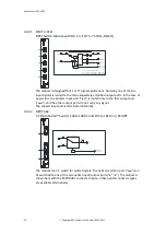
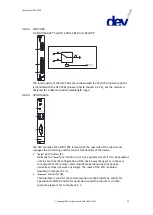
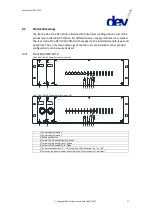
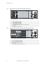
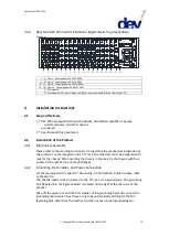
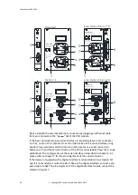
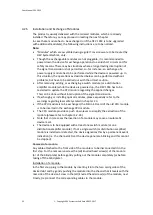
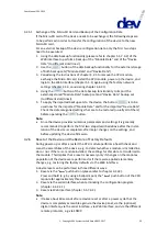
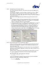
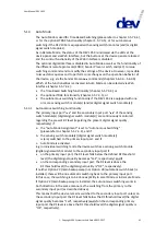
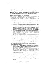
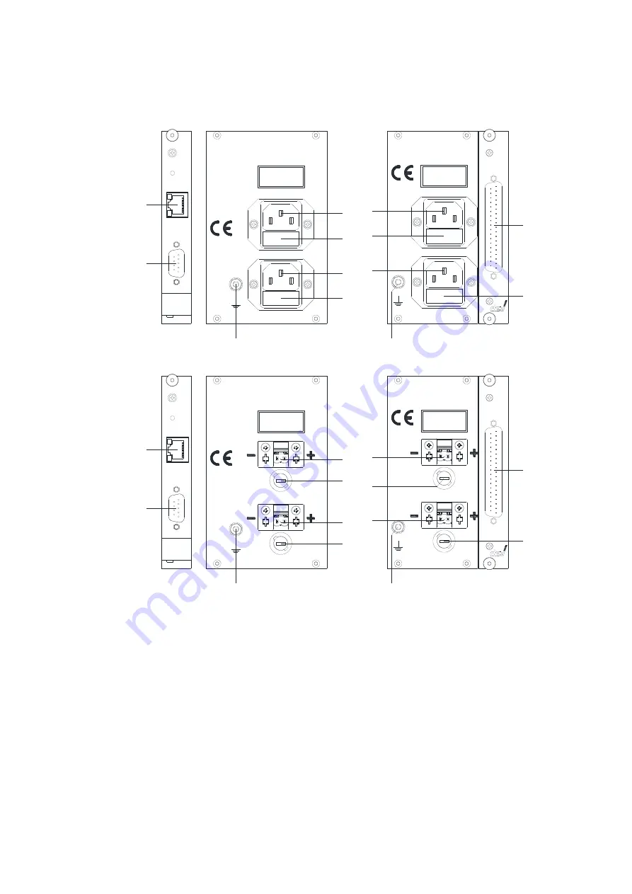
Next, establish the external Ethernet connection by plugging an Ethernet cable
from your network to the "
Ethernet
" (
3
) of the CPU module.
If the basic network setup via serial interface is required (please refer to chapter
4.4.2.2), and/or if it is intended to control the device via the serial interface using
Sandar Prosan protocol, Leitch protocol, or QEC protocol, a serial connection
between a PC and the serial connector of the CPU module labeled "
Com
" (
2
) is to be
established. The configuration of the serial interface is described in chapter 4.4.1;
please refer to chapter 7 for the pin assignment of the serial connector.
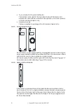
If the device is equipped with a digital interface module (Option 56 or Option 57)
and if it is intended to control the DEV 1953 via the digital interface, connect a pre-
pared cable to (
8
). The pin assignment of the digital interface module connector is
stated in chapter 7.

