background image

12

PRE-START CHECKS  & STARTING

pre-sTarT CheCKs

• Ensure you are wearing safety glasses and hearing protection.

• Avoid wearing loose fitting clothing.

• Place the machine on a level ‘dirt or grass’ surface.

• Check that all fasteners on the machine are secure and all guards are in place.

• Check engine oil level.

• Ensure the hopper and the chipping chamber are clear.

• Keep bystanders away.

• Follow safety instructions (page 9) when filling the fuel tank.

1. Disengage the clutch. Push the lever fully down..
2. Turn the fuel tap to ‘ON’. 
3. Switch on the ignition. 
4. Push the throttle lever to ‘FAST’. (Rabbit)
5. Move the choke control to ‘CHOKE’.( Generally not necessary if the engine is hot.)
6.  Stand  facing  the  engine  control  panel  and  to  the  right  of  the  panel.  With  your  left  hand 

holding the top of the hopper and your right hand holding the starting cord handle, swiftly pull 

the starting handle to the right. Repeat until the engine starts. If the engine seems to be flooded, 

you may need to try a few pulls of the starter with the choke fully off.
7. As soon as the engine fires, start reducing the choke setting. 
8. Once the engine sounds stable, and the choke is fully off, slowly raise the clutch lever until 

it reaches the end of its stroke.
9.  Check  that  the  rotor  is  spinning  by  looking  down  inside  the  hopper.  If  it  is  not  spinning, 

maintenance is required. (See ‘Maintenance’ section - page 15).
10.  Reduce the throttle setting to the position you need for effective machine operation. Large 

diameter branches or a heavy shredding load will require full throttle.

imporTanT: The clutch is fitted to make starting easier. it may not fully disengage the drive 

to the rotor, especially when the drive belt is new. neVer rely on the clutch to disengage the 

drive. 

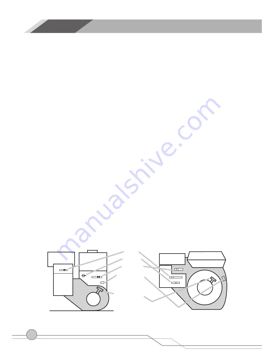
sTarTinG   (see engine diagram below)

Control Panel Layout (B&S)

Control Panel Layout (Honda)

CHOKE

FUEL TAP

THROTTLE

ON-OFF SWITCH

STARTER  HANDLE

6.0

Summary of Contents for GARDEN CHIPPER 750

Page 1: ...Operation and Maintenance Manual www deutschermowers com au GARDEN CHIPPER 750 DEUTSCHER...

Page 2: ......

Page 3: ...l Assembly Safety Procedures Decals Storage Transporting Pre Start Checks Starting Chipping Basic Maintenance Detailed Maintenance Exploded View Drawing Parts List Warranty Contact Details INDEX 5 6 8...

Page 4: ......

Page 5: ...tting device rotor of the Garden Chipper 750 is a 395mm diameter 8mm thick steel disk with twin tool steel chipper blades bolted to its surface To eliminate the possibility of material wrapping around...

Page 6: ...washer for securing the discharge chute 3 Place a 16mm washer on each end of the base frame axle then put the two wheels on the axle followed by another washer on the outside of each wheel Push the 2...

Page 7: ...rd M8 x 20 bolt plus an 8mm plain washer and an 8mm spring washer have been provided for locking the chute in the operating position With the chute lowered place the spring washer then the plain washe...

Page 8: ...bolts and other fasteners are properly secured and that guards and covers are in place 9 Replace damaged or unreadable labels See Decals section page 10 10 Use extra care in handling fuels They are fl...

Page 9: ...ed parts replaced or repaired with parts of equivalent specifications 8 Do not allow processed material to build up in the discharge zone this may prevent proper discharge and may result in kickback o...

Page 10: ...owers Pty Ltd as a set See Parts List page 20 in this manual On the top under underneath the discharge chute Part No 3350 On the side of hopper Part No 3498 On belt guard near clutch lever On the top...

Page 11: ...se across steep slopes The unit may fall sideways 2 Do not attempt to move the unit up or down stairs unless you are capable of holding the weight Always proceed slowly down stairs with the unit below...

Page 12: ...le swiftly pull the starting handle to the right Repeat until the engine starts If the engine seems to be flooded you may need to try a few pulls of the starter with the choke fully off 7 As soon as t...

Page 13: ...hrough the base opening simply cut off the large end with a bow saw 2 If the engine is slowing significantly as a branch is being processed check that the throttle is set to Fast and allow the disc to...

Page 14: ...charge opening to remove the offending material WARNING FAILURE TO FOLLOW ALL THESE PROCEDURES COULD LEAD TO A SERIOUS INJURY AS THE ENGINE MAY START WHEN THE DISC IS ROTATED BY HAND 8 Be very careful...

Page 15: ...ents etc Oil check and replacement The engine oil level should be checked regularly every 4 hours of operation For oil replacement see the engine manual Air filter cleaning Check the condition of the...

Page 16: ...g cover plate above the discharge chute and the M8 bolt and nut that secure the side cover plate adjacent to the sloping cover plate Remove both plates With the clutch lever disengaged turn the rotor...

Page 17: ...f the engine near the clutch handle then removing the four bolts securing the engine to its base plate Lift the engine off the unit Remove the discharge chute Remove the four screws attaching the chas...

Page 18: ...NOTE When re assembling ensure the shoulder on the spindle shaft is hard against the inside bearing Next the pulley boss must be positioned fully in against the outside bearing with the boss screws o...

Page 19: ...31 26 32 29 27 28 33 23 35 36 39 40 41 6 43 44 66 46 48 51 52 53 54 55 56 57 58 59 1 2 3 5 6 4 7 8 9 10 11 14 12 16 15 37 38 14 14 14 14 14 14 18 13 8 8 8 8 8 8 8 8 22 27 14 31 36 8 34 8 36 36 30 36...

Page 20: ...nda 1 11 3162 KEY 3 16 x 37mm 1 12 3446 Engine Pulley assembly 1 13 1521 Set screw for pulley 3 14 1019 8mm Plain washer 21 15 1018 8mm Spring washer 2 16 3495 Belt guide rydal bar 2 17 1100 Bolt 5 16...

Page 21: ...icroswitch screw 2 36 1017 Bolt M8 x 20 12 37 3432 Discharge chute assembly 1 38 3486 Microswitch bracket 1 39 3437 Rear Plate Welded Assembly 1 40 3494 Rear belt guard metal 1 41 3479 Star Washer 2 4...

Page 22: ...Circlip 2 59 1315 5 8 Washer 4 60 1118 M8 bolt x 35 1 61 3455 Maintenance cover side plate 1 62 3456 Maintenance cover top plate 1 63 1342 M8 x 25 bolt 2 64 3474 Angle iron fan blade 4 65 3478 Remova...

Page 23: ...NOTES...

Page 24: ...e owner must return the chipper at the owners expense to an authorized dealer then give the authorized dealer a clear explanation of the defect A list of authorized dealers can be found on the Deutsch...

Reviews: