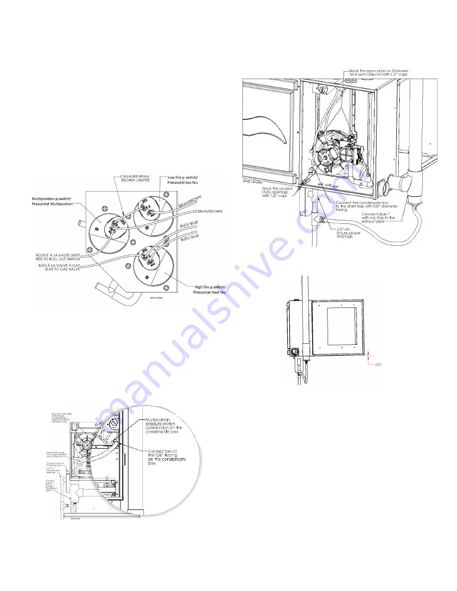
tubing to connect the pressure switch (-0.2 in. w.c.) to this stub.
(see figure 5)
The pressure switch must also be electrically connected in
series with the low fire pressure switch (top) using the brown
jumper provided in the parts bag. Refer to figure 4 for more
details.
Figure 4 –
Downflow position pressure switch
assembly
Figure 5 – Connecting pressure switch in downflow
position
3.3
HORIZONTAL RIGHT
Figure 6 – Horizontal right position
Figure 7 – Horizontal right slope
When installing the furnace in horizontal right position, make
sure the furnace is tilted foward to make it drain properly. Refer
to figure 7.
Plan your installation and make sure you have sufficient space
for the drain trap and exhaust pipe drainage. Drain trap will add
approximately 6.50" to the furnace width. Refer to figure 6.
3.3.1
Horizontal right condensate drain
trap connection
REFER TO FIGURE 6 FOR INSTALLATION DETAILS
1. Remove all condensate tubings from the inducer blower
and vent collector. Block the openings with provided 5/8"
and 1/2" black caps.
2. Remove the horizontal right drain trap knock-out.
3. Place the gasket on the drain trap.
4. Screw the drain trap in place with 2 self-tapping screws
to the side of the furnace.
11
Summary of Contents for C105-2-V
Page 24: ...Figure 29 Direct vent clearance 23 ...
Page 25: ...Figure 30 Other than Direct vent clearance 24 ...
Page 32: ...Figure 31 Dimensions 31 ...
Page 33: ...Figure 32 Two Stage ECM Wiring diagram 32 ...
Page 36: ...Figure 33 Exploded view Cxx 2 V part 1 35 ...


