Page 6
2) Work the front dress panel over the switches and then down the switch bushings slightly. You
don’t need to push the panel all the way down to the switch body.
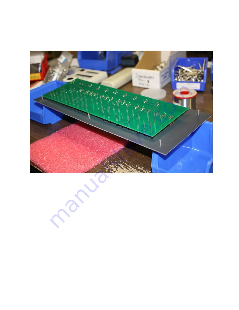
3) Turn the PCB/front panel over as shown below and let the LEDs fall into the front panel LED holes.
If the front panel sags a bit in the middle, add a third support point near the middle of the panel.
4) Carefully adjust the spacing between the PCB and the front panel in order to accommodate the
four 5/8” spacers provided*. The goal is to make the PCB and front panel as parallel as possible.
The spacers are used only for this step – they do not remain in the assembly. (Note that once an
LED is soldered, it can then serve as a “spacer”)
See the pictures on the next page
.
5) Push each LED all the way down into its corresponding front panel hole. Re-verify that the front
panel and PCB look perfectly parallel to each other and are resting directly on all of the white
spacers.
See the pictures on the next page.
6) Solder the LEDs: Press down gently on the PCB with your “spare” fingers as you solder the LEDs to
the PCB. You may want to slide the white spacers near the area you are working as you proceed
through the LEDs. Note that once an LED is soldered, it can then serve as a “spacer.”
* The spacer height determines how far the LEDs will protrude through the front panel after final as-
sembly. With APEM switches in the Altair Clone case, a spacer height of 5/8” to 11/16” gives a good
LED position after final assembly. At 5/8”, the LEDs protrude just slightly through the front panel. At
11/16”, the LEDs protrude a bit further. You can add something thin under each 5/8” spacer to raise it
towards 11/16” depending on your LED position preference. The
spacing requirement is different
if
you use a different switch brand since switch body height varies slightly between brands.


![Lenovo 90B6 [H50-50 ES] User Manual preview](http://thumbs.mh-extra.com/thumbs/lenovo/90b6-h50-50-es/90b6-h50-50-es_user-manual_201023-01.webp)


