26
DVD-2910/955
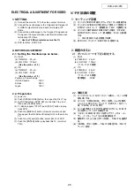
ELECTRICAL ADJUSTMENT FOR VIDEO
1. SETTING
(1) Connect the monitor TV to the video output terminal.
(2) Connect the oscilloscope to the Y-signal and C-signal of
S-VIDEO output terminal and each terminate at 75
Ohms.
(3) Connect the oscilloscope to the Y-signal, P
B
-signal and
P
R
-signal of Component video output terminal and each
terminate at 75 Ohms.
※
Use the 75 Ohms resistance must be 1%
(4) DVD test disc : DVDT-S01
2.
BEFORE ADJUSTMENT
2.1. Setting the Oscilloscope as below.
(1) P
B
/P
R
(a) TIME/DIV : 20
μ
S
(b) VOLT/DIV : 100mV
(Use the probe : x10 )
(2) Y/C
(a) TIME/DIV : 20
μ
S
(b) VOLT/DIV : 50mV
(Use the probe : x10 )
Power on. Power Supply
USA & Canada
:
120V
Europe
:
230V
Japan
: 100V
2.2. Preparation
(1) power on.
(2) Push [OPEN/CLOSE] button, then open the Disc Tray.
(3) Set DVD test disc (DVDT-S01) on the Disc Tray, and
then push [CLOSE] button.
(4) FL display appear “STOP”, push [PLAY] button to play-
back DVD.
(5) Push the [DISPLAY] button of remote control unit and
then appear the ON-Screen Display (GUI) on the monitor
TV.
(6) Push the [+10] and [2] button, select title 12 of DVD.
(7) Push the [ENTER] button, playback title 12. (color bar
75%)
ビデオ回路の調整
1. セッティング手順
(1) セットの VIDEO OUT 端子にテレビモニターを接続する。
(2) セットの S2 VIDEO OUT 端子から Y 信号と C 信号をそ
れぞれオシロスコープ(終端抵抗:75Ω)に接続する。
(3) セットの COMPONENT VIDEO OUT の端子(Y/P
B
/P
R
)
をそれぞれオシロスコープ(終端抵抗:75Ω)に接続
する。
※ 75Ω 抵抗は 1%品を使用する事。
(4) DVD テストディスク:DVDT-S01 を用意する。
2. 調整のまえに
2.1. オシロスコープを下記に設定する。
(1) P
B
/P
R
(a) TIME/DIV : 20
μ
S
(b) VOLT/DIV : 100mV
(プローブ x10 使用)
(2) Y/C
(a) TIME/DIV : 20
μ
S
(b) VOLT/DIV : 50mV
(プローブ x10 使用)
電源電圧 :100V
2.2. 準備手順
(1) セットの AC コードをコンセントへ挿入し、セットの電
源を ON する。
(2) セットの「OPEN/CLOSE」ボタンを押しトレイを開き、
トレイ上に DVD テストディスク(DVDT-S1)をセット
後、「CLOSE」ボタンを押す。
(3) セット表示管上に "STOP" が表示されてから、PLAY ボ
タンを押し、ディスクを再生する。
(4) リモコンの DISPLAY ボタンを押しグラフィカル・ユー
ザー・インターフェイス (GUI) 画面を出す。
(5) 番号ボタンの [+10][2] ボタンを押し、Title 12 を選択す
る。
(6) 「ENTER」ボタンを押し、Title 12 を再生する(75%カ
ラーバー信号)。
Summary of Contents for DVD-2910
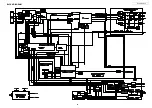
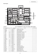
Page 29: ...29 DVD 2910 955 BLOCK DIAGRAM ...
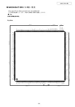
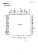
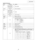
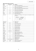
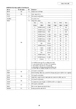
Page 48: ...48 DVD 2910 955 CXD2753R IC602 Pin Assignment Block Diagram ...
Page 79: ...79 DVD 2910 955 TA76432FC IC902 PC123 IC909 COLLECTOR EMITTER ANODE CATHODE TOP VIEW ...
Page 81: ...81 DVD 2910 955 PRINTED WIRING BORDS GU 3612 MAIN PWB P W B UNIT ASS Y COMPONENT SIDE ...
Page 82: ...82 DVD 2910 955 GU 3612 MAIN PWB P W B UNIT ASS Y FOIL SIDE ...
Page 83: ...83 DVD 2910 955 GU 3615 VODEO P W B UNIT ASS Y COMPONENT SIDE ...
Page 84: ...84 DVD 2910 955 GU 3615 VODEO P W B UNIT ASS Y FOIL SIDE ...
Page 85: ...85 DVD 2910 955 GU 3616 AUDIO POWER P W B UNIT ASS Y COMPONENT SIDE ...
Page 86: ...86 DVD 2910 955 GU 3616 AUDIO POWER P W B UNIT ASS Y FOIL SIDE ...
Page 117: ...DVD 2910 955 117 GU 3615 1 VIDEO P W B V6 V7 V8 V1 V2 V3 V4 V5 ...

