background image

ENGLISH

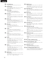
(2)  Rear Panel

q

DIGITAL IN (AES/EBU) connector

This is an active balanced input using an XLR type connector.

Connect this connector to the balanced digital output
connector on an amplifier or console.

Signal format: AES/EBU or IEC958 Type 

II

Pin layout: 

1. Common
2. Cold
3. Hot

Applicable connector: Cannon XLR-3-32 or equivalent.

w

DIGITAL OUT (AES/EBU) connector

This is an active balanced output using an XLR type
connector.

Connect this connector to the balanced digital input
connector on an amplifier or console.

Signal format: AES/EBU

Pin layout: 

1. Common
2. Cold
3. Hot

Applicable connector: Cannon XLR-3-31 or equivalent.

11

y

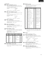
RS232C/RS422A selector switch

Use this to switch the serial remote connector signal
between RS232C and RS422A according to the external
controller’s signal.

NOTE:

The tally output pin has open collector IC specifications
(Imax. 20 mA, Vmax. 5V), but the maximum supply
current is 80 mA, so use with a total load current of 80
mA or less.

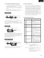
Pin no.

1

6

2

7

3

8

4

9

5

Signal name

NC

NC

T

X

D

NC

R

X

D

NC

NC

NC

S.GROUND

I/O

O

I

I/O

O

O

I

I

Signal name

NC

S.GROUND

T

X

D (RETURN)

T

X

D

R

X

D

R

X

D (RETURN)

NC

NC

NC

RS232C

RS422A

i

AC inlet

Connect the included power cord here.

o

ANALOG IN (BALANCED) connectors

These are active balanced inputs using XLR type connectors.

Connect these connectors to the balanced analong output
connectors on an amplifier or consoe.

Pin layout:

U.S.A. & Canada

Europe , Asia & Others

1. Common

1. Common

2. Cold

2. Hot

3. Hot

3. Cold

Applicable connector: Cannon XLR-3-32 or equivalent

!0

ANALOG IN (UNBALANCED) jacks

These are unbalanced inputs using RCA type jacks.

Connect these jacks to the unbalanced analong output jacks
on an amplifier or consoe.

!1

ANALOG OUT (UNBALANCED) jacks

These are unbalanced outputs using RCA type jacks.

Connect these jacks to the unbalanced analog input jacks on
an amplifier or console.

Pin no.

1

14

2

15

3

16

4

17

5

18

6

19

7

20

8

21

9

22

10

23

11

24

12

25

13

Signal name

I/O

FG

PLAY tally

PLAY command

PAUSE tally

PAUSE command

STDBY/CUE tally

STDBY/CUE commad

END CUE tally

TRACK (+) commad

Tally common

TRACK (–) commad

REC command

SEARCH (FWD) command

CUE tally

SEARCH (REV) command

REC tally

FADER START command

Tally power supply

Command common

Command common

Reserved

E.O.M. tally

Reserved

Reserved

Hot Start Mode (High)

O

I

O

I

O

I

O

I

I

I

I

O

I

O

I

O

I

TTL (lol=20mA)

HCMOS (li–3mA)

TTL (lol=20mA)

HCMOS (li–3mA)

TTL (lol=20mA)

HCMOS (li–3mA)

TTL (lol=20mA)

HCMOS (li–3mA)

HCMOS (li–3mA)

HCMOS (li–3mA)

HCMOS (li–3mA)

TTL (lol=20mA)

HCMOS (li–3mA)

TTL (lol=20mA)

PHOTO COUPLER

+5V, 20mA

(li=10mA)

TTL (lol=20mA)

HCMOS (li–3mA)

e

DIGITAL IN (SPDIF) jack

This is an unbalanced input using an RCA type jack.

Connect this jack to the unbalanced digital output jack on an
amplifier or console.

Signal format: SPDIF or IEC958 Type 

II

r

DIGITAL OUT (SPDIF) jack

This is an unbalanced output using an RCA type jack.

Connect this jack to the unbalanced digital input jack on an
amplifier or console.

Signal format: SPDIF or IEC958 Type 

II

t

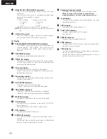
RS232C/RS422A connector

This is a serial remote connector. A personal computer or
other external controller can be connected to control the DN-
M1050R externally.

Applicable connector: 9-pin D-sub (female)

Baud rate: 9600 bps or 19200 bps

Pin layout:

u

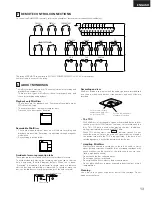
REMOTE connector

This is a parallel remote connector. Use it to control the DN-
M1050R with dry contact circuit connections.

Applicable connector: 25-pin D-sub (male)

Connector signal layout:
Summary of Contents for DN-M1050R

Page 1: ......

Page 2: ......

Page 3: ...nly as recommended by the manufacturer 15 Power Lines An outdoor antenna should be located away from power lines 16 Outdoor Antenna Grounding If an outside antenna is connected to the receiver be sure...

Page 4: ......

Page 5: ......

Page 6: ...B 2 Finish mode Stop Next Recue only when Single Track play is selected I Stop Stop after finishing to play a track II Next Standby at the beginning of next track after finishing to play a track III R...

Page 7: ...ing Two Tracks Combine function 32 8 Moving Tracks Move function 33 9 Inserting Specfic Sections A B insert function 34 10 Inputting Changing Names Title function 35 11 Undoing Editing Undo functions...

Page 8: ...2 PROG PLAY ON OFF button When this button is pressed while the PROGRAM IN button is lit the program play mode is set The button will not function during the A B play mode The button lights during the...

Page 9: ...NSERT button Press this button in the edit mode to set the insert mode to insert any section When the button is pressed again after setting the A and B points Insert PT appears on the display 9 COMBIN...

Page 10: ...nnect these jacks to the unbalanced analong output jacks on an amplifier or consoe 1 ANALOG OUT UNBALANCED jacks These are unbalanced outputs using RCA type jacks Connect these jacks to the unbalanced...

Page 11: ...s or flashes when the digital input signal is selected The indicator flashes when the digital signal is unlocked and remains lit when the digital signal is locked 2 Sampling frequency display This dis...

Page 12: ...pt to record erase or otherwise edit the disc and the recording is protected To record or erase the disc set the tab back to its original position with the hole covered Recording on discs MiniDiscs in...

Page 13: ...USE button Playback begins and the playback signals are output The end is monitored then the pickup returns to the play start position and the standby mode is set End Monitor NOTE If the STANDBY CUE b...

Page 14: ...d This eliminates fluctuations of the A D converter DC offset reduces the amount of DC offset at the recording start position in the middle of the recording and at the recording end position and keeps...

Page 15: ...ecording analog inputs use the INPUT LEVEL controls to adjust the recording level For digital input For analog input For unbalanced input For balanced input Lit MIN MAX Adjust the left and right contr...

Page 16: ...incremented NOTE The auto track increment function using the DAT s start ID or the CD s sub codes will not work if the digital input is in professional format AES EBU Input digital signals of the cons...

Page 17: ...discs at different speeds The speed can be changed with the range of 9 9 to 9 9 When the dial is turned clockwise the playback position moves as follows Listen to the sound and find the desired play s...

Page 18: ...model Press the TITLE IN button 6 1 m s f TRACK NO SINGLE REMAIN NEXT NO TOC TOC WRITE TOC WRITE Write the UTOC Press the TOC WRITE button Lit Lit Flashing or Off Off Off Off Lit Lit TOC WRITE TOC WR...

Page 19: ...the desired play end point 6 3 Set the new B point or A point Press the B or A button To change the B point B B B 6 4 Cue to A point Press the A button 7 Set the A B play mode Press the PLAY MODE but...

Page 20: ...g Lit Lit Lit Lit 5 Stopping playback Playback can be stopped in the following ways PLAY PAUSE PLAY PAUSE STANDBY CUE STOP STANDBY CUE STANDBY CUE 6 Canceling the repeat mode during playback Press the...

Page 21: ...al and input level referring to steps 4 and 5 under Starting Recording on Page 16 5 Start recording Press the PLAY PAUSE button Recording starts when an input signal with a level at or above the set l...

Page 22: ...ich you want to set the cue point 3 1 Set the cue point Press the CUE WRITE button EDIT EDIT EDIT CUE WRITE CUE WRITE 3 2 Press the CUE WRITE button again while Cue Write OK is displayed 4 To continue...

Page 23: ...SEARCH 3 1 Search for the cue point Press the STANDBY CUE button The Cue1 point is searched for and the standby mode is set at that position Press the STANDBY CUE button again to search as follows ST...

Page 24: ...s f TRACK NO SINGLE REMAIN 5 Exit the program input mode Press the PROGRAM IN button The set returns to the normal mode IN PROGRAM IN PROGRAM IN PROGRAM The step number flashes Flashing Flashing Sele...

Page 25: ...Delete that track from the program Press the button To continue deleting tracks from the program repeat steps 11 1 and 11 2 I TRACK NAME m s f TRACK NO SINGLE REMAIN 12 Exit the program editing mode P...

Page 26: ...t Program 1 or Program 2 or Program 3 2 3 Change the preset setting Press the select knob 2 4 Cancel the preset mode Press the PLAY MODE button PLAY MODE Character display Select one of these The char...

Page 27: ...Track A Track B Track B Track C Track C Track D Track D Point where track was divided Point where tracks were combined Combine function for combining two tracks Short recordings or cuts created by di...

Page 28: ...track to be erased can be selected or changed by turning the select knob ERASE m s f TRACK NO SINGLE REMAIN NEXT NO EDIT 5 2 Press the ERASE button again The track is erased and the mode returns to th...

Page 29: ...if no A B points are set 5 1 Set the standby mode at the position of the cue signal you want to erase Press the CUE SERCH button The cue direct search mode is set CUE SEARCH CUE SEARCH 5 2 Press the...

Page 30: ...ection is rehearsed and is displayed the first time the ERASE button is pressed Press the ERASE button again ERASE ERASE 9 2 Press the ERASE button again The A B section is erased and the mode returns...

Page 31: ...the EDIT button 3 Select the tracks to be combined Use the select knob to set the standby mode at the second of the tracks to be combined 4 Set the combine mode Press the COMBINE button COMBINE m s f...

Page 32: ...INGLE REMAIN NEXT NO EDIT 4 Set the move mode Press the MOVE button MOVE EDIT m s f TRACK NO SINGLE REMAIN NEXT NO 5 Turn the select knob to select the destination of the track 6 Move the track Press...

Page 33: ...edit mode Press the EDIT button EDIT EDIT m s f TRACK NO SINGLE REMAIN NEXT NO EDIT 7 2 Set the insert mode Press the INSERT button NOTE If both the A and B points are set the A B section is rehearsed...

Page 34: ...ess the select knob Lit Lit Lit Flashing Capital letters Small letters Num bers Symbols Flashing cursor Flashing 7 Continue inputting the name Repeat steps 5 1 5 2 and 6 to input the name Turn the SEA...

Page 35: ...isplayed EDIT EDIT m s f TRACK NO SINGLE REMAIN NEXT NO TOC EDIT 3 Select the undo mode Turn the select knob UNDO For undoing the last editing operation REDO For resetting the editing undone with the...

Page 36: ...A and B points are the same A B insert operation A point is the beginning of the track A B insert operation B point is the end of the track A B insert operation Inserting is not possible because there...

Page 37: ...2 F3 F4 F5 F6 F7 F8 F9 F10 F11 F12 Print Scrol Pause Ins Home PgUp NumLk Home PgUp End PgDn 7 8 9 4 5 6 1 2 3 Enter Ins 0 Del Del End PgDn Track search reverse 1 track Track search forward 1 track PLA...

Page 38: ...t track PUSH ENTER operation Ins Del Enter Ins Del Del BackSpace Esc Enter Number keys Letter keys Q to P Hot start 11 to 20 Hot start 1 to 10 Number keys Letter keys Q to P Reload data 11 to 20 Reloa...

Page 39: ...et OFF Auto Inc OFF Inc Det 60dB Pre UTOC OFF UTOC Manual RecStart 60dB Rec Offset OFF Rec Stereo SCMS INH PichAuto OFF Sleep ON 1 2 3 4 5 6 7 8 9 10 11 12 13 FS OFF End Mon 10s 14 20 Hot start Date d...

Page 40: ...ile holding in both the PLAY MODE and the END MON buttons For the initial settings refer to 1 List of preset functions LAY MODE END MON 3 Change the preset values Press the select knob 2 Select the pr...

Page 41: ...C OFF Pre UTOC function off Pre UTOC ON Pre UTOC function on 7 UTOC Manual Auto UTOC Manual UTOC is written by pressing TOC WRITE button after editing is completed UTOC Auto UTOC is written automatica...

Page 42: ...rack when the STANDBY CUE button is pressed during playback 24 PlayLock ON OFF PlayLock ON Inhibit all operations other than the PLAY PAUSE TIME and PLAY MODE buttons during playback PlayLock OFF Enab...

Page 43: ...ng the REC button during recording Recording is not possible because of a problem in the TOC recording enable data Indicates that editing is complete Indicates that the cue search operation is being p...

Page 44: ...e the maximum number of tracks is reached even if they take up less than the maximum recordable time To record on such discs first erase unneeded tracks When this is done it is not possible to record...

Page 45: ...ter 92 dB or higher Playback A filter 84 dB or higher Recording A filter 86 dB or higher Playback A filter 80 dB or higher Recording A filter 1 kHz 0dB playback Balanced active XLR connector Unbalance...

Page 46: ......

Reviews: