background image

Specifications

[Display]

1

. S p   2 . I n   3 . O p

Q

S p e a k e r   S e t u p

Q

8       F L     :     1 2 f t

Q

1 5   S W       :     1 2 f t

k

 ~ 

A5 

Distance

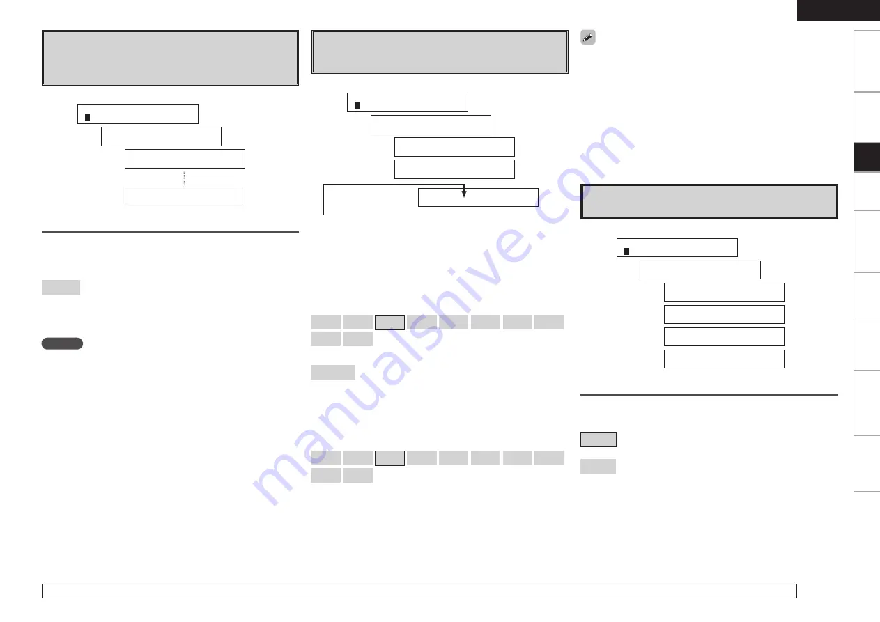
Set distance from listening position to speakers.
Before  making  the  settings,  measure  the  distance  from  the 
listening position to the different speakers.

Distance measurement

Select the speaker you want to set, then set the distance.
Set the value closest to the measured distance.

[Variable range]

0ft ~ 60ft

 :   Settable in units of 1 foot.

Default setting :
• FL / FR / C / SW  ·············12 ft
• SL / SR / SBL / SBR  ········10 ft

NOTE

Set  the  distance  between  the  listening  position  and  the  various 
speakers to no more than 20 ft.

A6

 ~ 

S1 

Crossover Frequency

Select crossover frequency from which subwoofer handles low 
range signal.

Only  the  portion  of  the  bass  sound  of  the  various  speakers  output 
from  the  subwoofer  that  has  a  frequency  below  the  frequency  set 
here is output.
Set  this  according  to  the  low  frequency  reproduction  capabilities  of 
the speakers you are using.

[Selectable items]

40Hz


60Hz


80Hz


90Hz


100Hz


110Hz


120Hz


150Hz


200Hz


250Hz

 :

Set the Crossover Frequency of all speakers as one. 

Advanced

 :

Set the Crossover Frequency separately for the different speakers.

When “Cr.Over:Adv” is displayed, press 

ENTER

 or 

i

w  

Press 

o


p

 to set the crossover frequency of each speaker. 

  The preset speaker changes each time you press 

i

.

[Selectable items]

40Hz


60Hz


80Hz


90Hz


100Hz


110Hz


120Hz


150Hz


200Hz


250Hz

In the case of “LFE”, there are 8 modes: 80Hz, 90Hz, 100Hz, 110Hz, 
120Hz, 150Hz, 200Hz, 250Hz.

• If in the “Advanced” settings, “Subwoofer Mode Setup” (

v

page 

23) in the “System Setup” is set to “Norm”, it is possible to make 
this setting for speakers set to “Small” at “Speaker Configuration”. 
If set to “+Main”, this setting can be made regardless of the speaker 
size.

• For speakers set to “Small”, sound below the crossover frequency 

is cut from the sound output. The cut bass sound is output from the 
subwoofer or front speakers.

• Always set the crossover frequency to “80Hz”. When using small 

speakers, however, we recommend setting the crossover frequency 
to a higher frequency.

S2 

Test Tone

Adjust channel levels to obtain equal volume from all speakers.

Test Tone

Select test tone playback method.

[Selectable items]

Auto

 :  Automatically  switch  speaker  from  which  test  tone  is 

output.

Manual

 :  Manually switch speaker from which test tone is output.

For details on how to select, set and cancel settings for each menu, see “System setup operation” (

v

page 22).

Getting Started

Connections

Setup

Playback

Remote Control

Multi-Zone

Information

Troubleshooting

ENGLISH

[Display]

1

. S p   2 . I n   3 . O p

Q

S p e a k e r   S e t u p

Q

1 6 C r . O v e r :   8 0 H z

Q

1 6 C r . O v e r : A d v

Q

1 7   C r . F     :   8 0 H z

F : Front, C : Center, S : Surround, SB : Surround Back, LFE : LFE are 
displayed.

[Display]

1

. S p   2 . I n   3 . O p

Q

S p e a k e r   S e t u p

Q

2 2   T . T o n e     Y e s <

Q

T . T o n e     A u t o   >

Q

T e s t   T o n e   O n

Q

          A u t o - F L

Summary of Contents for AVR 689 - AV Receiver

Page 1: ...AV SURROUND RECEIVER AVR 689 Owner s Manual Manuel de l Utilisateur ...

Page 2: ...ely to be walked on or pinched by items placed upon or against them paying particular attention to cords at plugs convenience receptacles and the point where they exit from the product 15 Outdoor Antenna Grounding If an outside antenna or cable system is connected to the product be sure the antenna or cable system is grounded so as to provide some protection against voltage surges and built up sta...

Page 3: ...must accept any interference received including interference that may cause undesired operation 2 IMPORTANT NOTICE DO NOT MODIFY THIS PRODUCT This product when installed as indicated in the instructions contained in this manual meets FCC requirements Modification not expressly approved by DENON may void your authority granted by the FCC to use the product 3 NOTE This product has been tested and fo...

Page 4: ...Playback 32 Getting Started Connections Operations Preparations 19 Auto Setup 20 a Auto Setup 20 s Error Messages 21 System setup operation 22 Example of Display of Default Values 22 1 Speaker Setup 23 a h Speaker Configuration 23 j Subwoofer Mode Setup 23 k A5 Distance 24 A6 S1 Crossover Frequency 24 S2 Test Tone 24 S3 Restore 25 2 Input Setup 25 a d HDMI In Assign 25 f j Digital In Assign 26 k i...

Page 5: ...o Components 47 Presetting 47 Operating Preset Components 47 Punch Through Function 50 Getting Started Accessories Preparations 39 Turning the Power On 39 Selecting the Input Source 39 Setting the Input Mode 39 Operations During Playback 40 Playing Video and Audio Equipment 40 Basic Operation 40 Listening to FM AM Broadcasts 40 Basic Operation 40 Presetting Radio Stations Preset Memory 41 Listenin...

Page 6: ...tion improperly or the remote control unit may not operate if the remote control sensor is exposed to direct sunlight strong artificial light from an inverter type fluorescent lamp or infrared light Getting Started Connections Setup Playback Remote Control Multi Zone Information Troubleshooting ENGLISH About the Remote Control Unit Before turning the power switch on Check once again that all conne...

Page 7: ...ER knob on the main unit operates in the same way as the cursor o and p buttons on the remote control unit The control functions in the same way as the cursor o button when turned counterclockwise as the cursor p button when turned clockwise The control functions in the same way as the ENTER button when pressed the knob E6DYNAMIC VOLUME button 36 b About Dynamic Volume Audyssey Dynamic Volume solv...

Page 8: ... connectors 14 tREMOTE CONTROL jacks 17 yPRE OUT connector 9 uAC OUTLETS 17 iPower cord 17 oSpeaker terminals SPEAKERS 9 51 52 Q0FM AM antenna terminals TUNER ANTENNA 16 Q1COMPONENT VIDEO connectors 11 13 Q2HDMI connectors 10 11 13 Q3SIRIUS connector SATTU 15 Q4DOCK CONTROL jack 12 Getting Started Connections Setup Playback Remote Control Multi Zone Information Troubleshooting ENGLISH ...

Page 9: ...ct CH SEL ENTER button 22 45 q r w t y b u o Q2 Q1 i Q0 e qZONE2 power buttons 53 wSource select buttons 39 53 b To select SIRIUS as the input source use the SAT TU button eVideo select button V SEL 40 rTuner system buttons 40 41 tTest tone button TEST 25 yMain zone power buttons MAIN 53 uSurround mode buttons 31 32 iSystem setup button SYSTEM 22 oSurround parameter button PARA 31 33 Q0Enter butto...

Page 10: ...ect the cables according to the equipment being connected Preparations Connections NOTE Do not plug in the power cord until all connections have been completed When making connections also refer to the operating instructions of the other components Be sure to connect the left and right channels properly left with left right with right Do not bundle power cords together with connection cables Doing...

Page 11: ...ectors When a non standard video signal from a game machine or some other source is input the video conversion function might not operate When not using this function connect a monitor output with the same type of connector as the video input connector The illustration below shows a basic example of installation of the amplifier combined with 8 speakers and a monitor Speaker Installation Subwoofer...

Page 12: ...ct the speaker cables in such a way that they do not stick out of the speaker terminals The protection circuit may be activated if the core wires touch the rear panel or if the and sides touch each other v Protection circuit Never touch the speaker terminals while the power supply is connected Doing so could result in electric shock Protection circuit If the core wires touch the rear panel and the...

Page 13: ...at When connecting to a monitor etc equipped with a DVI D connector connection is possible using an HDMI DVI converter cable but depending on the combination of components in some cases the video signals will not be output When connecting using an HDMI DVI converter adapter the video signals may not be output properly due to poor connections with the connected cable etc NOTE The AVR 689 cannot be ...

Page 14: ...or The component video connectors may be indicated differently on your monitor For details see the monitor s operating instructions To play the sound by AVR 689 make analog or digital audio output connections to AVR 689 s audio input connectors The signals output from the HDMI connectors are only the HDMI input signals The same method can be used to connect an HDP High Definition Player such as a ...

Page 15: ...iPod With the default settings the iPod can be used connected to the VCR iPod connector To assign the iPod to a connector other than VCR iPod make the settings at System Setup Input Setup iPod Assign vpage 26 Use a DENON control dock for iPod ASD 1R ASD 11R ASD 3N or ASD 3W sold separately to connect the iPod to the AVR 689 For instructions on the control dock for iPod settings refer to the contro...

Page 16: ... the terminal to use and connect the device When recording via the AVR 689 the playback device s cable must be of the same type as the cable used to connect the AVR 689 s VCR OUT connector Example TV IN S Video cable VCR OUT S Video cable TV IN Video cable VCR OUT Video cable When using a component video cable for the video connection make the settings at System Setup Input Setup Component In Assi...

Page 17: ...ote Control Multi Zone Information Troubleshooting ENGLISH Component with Multi channel Output connectors 46 800 3 5 3 463306 3 463306 3 30 5 3 6 0 R L R L R L R L R L R L DVD player External decoder To play the analog input signals input to the EXT IN connectors press the INPUT MODE button on the main unit or the INPUT button on the remote control unit and select EXT IN vpage 39 The video signal ...

Page 18: ...og logo and channel names and logos are trademarks of SIRIUS Satellite Radio Inc n Positioning the Antenna For a consistent satellite signal the antenna must be positioned correctly Use the following map to determine which area you are in and position the antenna accordingly q w e r t SOUTH NORTH WEST SKY EAST HORIZON Area 1 Point the antenna toward the sky in the east northeast or southeast eithe...

Page 19: ...s close to the point of cable entry as practical n AM loop antenna assembly Remove the vinyl tie and take out the connection line Connect to the AM antenna terminals Bend in the reverse direction a With the antenna on top of any stable surface Mount b With the antenna attached to a wall Installation hole Mount on wall etc Connection of AM antennas 1 Push the lever 2 Insert the conductor 3 Return t...

Page 20: ...il all connections have been completed before connecting the power cord To household power outlet AC 120 V 60 Hz Power cord Connection to the AC outlets These outlets supply power to external audio equipment The power supplied from these outlets turns on and off together with the set s power switch Audio equipment with a total power consumption of 120 W 1 A can be connected Turning the Power On vp...

Page 21: ...Subwoofer Level Auto Preset Memory Parental Lock Edit Lock Code n Option Setup vpage 28 30 Amp Assign Volume Control Volume Limit Power On Level Mute Level ZONE2 Volume Control ZONE2 Volume Limit ZONE2 Power On Level ZONE2 Mute Level 2ch Direct Stereo Auto Surround Mode Direct Mode Setup Remote ID Setup b When the setup microphone is connected Parameter vpage 33 37 n Surround Parameter Mode Cinema...

Page 22: ...e for the subwoofer M M Example q Example w Measuring positions 1Press SPEAKERS to select the front speakers Front A Front B or Front A B 2Set Amp Assign to define how the amplifier for the surround back speaker channels is used vpage 28 3Connect the included calibrated setup microphone to the SETUP MIC jack on the main unit Auto Set Start is displayed 4Place the microphone at ear height on a trip...

Page 23: ...r fewer positions use i to display Calculate After completing a measurement position move the microphone to the next position Measure at 6 positions the main listening position and 5 other surrounding positions Although it is allowable to measure less than 6 positions it is recommended to measure 6 for best results NOTE Do not disconnect the setup microphone until the auto setup procedure is compl...

Page 24: ... it away Try again when the surroundings are quieter Check the speaker installation and the direction in which the speakers are facing Adjust the subwoofer s volume Caution Sp None The messages alternate FR Displayed speaker could not be detected The front L and front R speakers were not properly detected Only one channel of the surround speakers was detected Sound was output from the R channel wh...

Page 25: ...next settings Setup 2 1 Sp 2 In 3 Op 4 Q 1 Front Large 1 System Setup Q Speaker Setup 3 Selectable items Large Small In lists of selectable items or adjustable ranges the item surrounded by a border is the default value uiop ENTER AUDIO DELAY ENTER op ui SYSTEM SETUP uiop ENTER SYSTEM SETUP TEST Front Rear Button located on both the main unit and the remote control unit BUTTON Button only on the m...

Page 26: ...reproduction capabilities Small Select this when using small speakers without ample low frequency reproduction capabilities None Select this when no speaker is connected Yes Select this when a subwoofer is connected No Select this when no subwoofer is connected 2spkrs 1spkr Select the number of surround back speakers NOTE By default the AVR 689 s Amp Assign setting is set to ZONE2 To use as the su...

Page 27: ... each time you press i Selectable items 40Hz 60Hz 80Hz 90Hz 100Hz 110Hz 120Hz 150Hz 200Hz 250Hz b In the case of LFE there are 8 modes 80Hz 90Hz 100Hz 110Hz 120Hz 150Hz 200Hz 250Hz If in the Advanced settings Subwoofer Mode Setup vpage 23 in the System Setup is set to Norm it is possible to make this setting for speakers set to Small at Speaker Configuration If set to Main this setting can be made...

Page 28: ...st so that the volume is equal for all speakers e When the adjustments are completed press TEST For details on how to select set and cancel settings for each menu see System setup operation vpage 22 25 Getting Started Connections Setup Playback Remote Control Multi Zone Information Troubleshooting ENGLISH S3 Restore After the Auto Setup measurements it is possible to return those settings to the A...

Page 29: ...1 DVD Input source DVD HDP z1 TV CBL z2 VCR V AUX OFF z1 DVD is displayed z2 TV is displayed Selectable items ON Enable conversion OFF Disable conversion A2 A5 Video Convert Automatically convert video input signal to monitor output format Input terminals l Component video1 A0 Component video2 A1 Component video3 Default setting DVD HDP TV CBL VCR Display 1 Sp 2 In 3 Op W Input Setup W 12 DVD Conv...

Page 30: ...nnel set the radio reception limits Display 1 Sp 2 In 3 Op W Input Setup W 17EXT In SW 15 Display 1 Sp 2 In 3 Op W Input Setup W 18 Preset Start The default password is 0000 If you wish to change this password set the new password with Edit Lock Code If the password is incorrectly input Incorrect Code is displayed and proceed again from step q If the password input is 3 digits or less Enter 4 digi...

Page 31: ...t is 80 dB the set volume level 3 Option Setup Make various other settings a Amp Assign s f Volume Control g j ZONE2 Volume Control k A4 2ch Direct Stereo Custom A5 Auto Surround Mode A6 Direct Mode Setup A7 Remote ID Setup a Amp Assign The places where the surround back amplifier are used can be set freely according to the usage environment This makes it possible to output sound to rooms other th...

Page 32: ...tings for 2 channel mode playback k Setting To change the settings select ON Selectable items OFF Use the same settings as in Speaker Setup ON Make separate settings for 2 channel mode l Front Select front speaker size Selectable items Large Small Select front speaker size A4 Crossover Select crossover frequency from which subwoofer handles low range signal Selectable items 40Hz 60Hz 80Hz 90Hz 100...

Page 33: ...BY PLgx Cinema e Multi channel signals of Dolby Digital DTS or other multichannel format DOLBY DTS SURROUND b Default settings are indicated in Selectable items ON Use MultEQ OFF Do not use MultEQ A6 Direct Mode Setup Select MultEQ use for DIRECT mode playback A7 Remote ID Setup Set remote control ID Selectable items 1 2 3 4 NOTE When using the AVR 689 with only the included remote control unit RC...

Page 34: ...DIGITAL DOLBY DIGITAL EX DOLBY DIGITAL PLgx CINEMA DOLBY DIGITAL PLgx MUSIC DTS Surround Source DTS 5 1ch DTS ES Discrete 6 1 DTS ES Matrix 6 1 DTS 96 24 DTS SURROUND DTS PLgx CINEMA DTS PLgx MUSIC DTS NEO 6 DTS ES MTRX6 1 z1 DTS ES DSCRT6 1 z2 DTS 96 24 z3 z1 This is displayed when the input signal is DTS ES Matrix 6 1 z2 This is displayed when the input signal is DTS ES Discrete 6 1 z3 This is d...

Page 35: ...inal surround modes The surround parameters can be adjusted vpage 57 58 to achieve an even more realistic powerful sound field Selecting the surround mode Select by turning SELECT ENTER or pressing SIMU Selectable items 5CH 7CH STEREO z1 This mode is for enjoying stereo sound from all speakers ROCK ARENA This mode is for enjoying the atmosphere of a live concert in an arena JAZZ CLUB This mode is ...

Page 36: ...t signal The type of surround mode For details of which parameters can be adjusted in each surround mode see Surround Modes and Parameters vpage 57 58 a Mode s Cinema EQ d D Comp Dynamic Range Compression f LFE g Center Image h Panorama j Dimension k Center Width l DelayTime A0 Effect Level A1 Room Size A2 SB CH OUT A3 SW ATT Subwoofer Attenuation A4 Subwoofer A5 Tone Control A6 Bass A7 Treble A8 ...

Page 37: ...rent program sources we recommend setting to the values below Dolby Digital sources 0 dB DTS movie sources 0 dB DTS music sources 10 dB d D Comp Dynamic Range Compression Compress dynamic range difference between loud and soft sounds Selectable items OFF Turn dynamic range compression off Low Low setting Mid Middle setting High High setting When playing DTS sources this is only displayed for compa...

Page 38: ...ources including a discrete 6 1 channel signal identification signal A2 SB CH OUT for 2 channel sources Determine whether to use surround back speakers Selectable items ON The surround back channel signal is played OFF The surround back channel signal is not played If the settings of speakers for which None has been determined at Auto Setup are changed Audyssey Audyssey Byp L R and Audyssey Flat c...

Page 39: ...orrect frequency response and surround levels moment by moment at any user selected volume setting The result is bass response tonal balance and surround impression that remain constant despite changes in volume Dynamic EQ combines information from incoming source levels with actual output sound levels in the room a prerequisite for delivering a loudness correction solution Audyssey Dynamic EQ wor...

Page 40: ...pressed sources with very weak highs Mode2 RESTORER 96 Apply suitable bass and treble boost for all compressed sources Mode3 RESTORER HQ Optimized mode for compressed sources with normal highs About the RESTORER function Such compressed audio formats as MP3 WMA Windows Media Audio and MPEG 4 AAC reduce the amount of data by eliminating signal components that are hard for the human ear to hear The ...

Page 41: ...he settings Information on the main unit s various settings Status and on input signals Audio Input Signal is shown on the display The information displayed changes each time you press STATUS The information is displayed for several seconds before the display returns to its original condition Items to be checked Surround Mode Input signal Dialogue normalization Input function Input digital termina...

Page 42: ...ut Mode Set the input mode for this source When a digital signal is properly input the indicator lights on the display If the indicator does not light check the digital input connector assignment and the connections The surround mode cannot be set if the input mode is set to EXT IN Only set PCM and DTS when playing the respective signals Selectable items Auto Detect type of digital input signal an...

Page 43: ...et SOURCE CONTROL 1 to AUDIO and SOURCE CONTROL 2 to TUNER vpage 47 Remote Control Unit Operations 3Press BAND to select FM or AM 4Tune in the desired broadcast station qTo tune in automatically AutoTuning Press MODE to light the AUTO indicator on the display then use TUNING to select the station you want to hear wTo tune in manually ManualTuning Press MODE to turn off the display s AUTO indicator...

Page 44: ... Auto Preset Memory vpage 27 NOTE Preset stations are erased by overwriting them 1Press SHIFT to select the memory block A to G 2Press PRESET CHANNEL or CHANNEL to select the desired preset channel 1 to 8 n Default settings Auto tuner presets A1 A8 87 5 89 1 98 1 107 9 90 1 90 1 90 1 90 1 MHz B1 B8 520 600 1000 1400 1500 1710 kHz 90 1 90 1 MHz C1 C8 90 1 MHz D1 D8 90 1 MHz E1 E8 90 1 MHz F1 F8 90 ...

Page 45: ...erage uncensored talk and comedy world class entertainment news weather and more for your car home or office For more information visit sirius com or siriuscanada ca Sirius is available in the US for subscribers with addresses in the continental US and is available in Canada for subscribers with a Canadian address Required subscription plus compatible SIRIUS tuner and antenna are required and sold...

Page 46: ...low and high frequency components of compressed audio files and achieve a richer sound The default setting is Mode3 vpage 37 Press ON STANDBY or OFF and set the AVR 689 s power to the standby mode before disconnecting the iPod Also switch the input source to one to which iPod Assign is not assigned before disconnecting the iPod When using an ASD 3N or ASD 3W control dock for iPod refer to the resp...

Page 47: ...2Press ENTER or p Playback starts n Stopping playback temporarily During playback press ENTER or 1 Press again to resume playback n Fast forwarding or fast reversing During playback press and hold 6 to fast reverse or 7 to fast forward n To cue to the beginning of a track During playback press 8 or 9 n To stop During playback either press and hold ENTER or press 2 n Playing repeatedly Press TUNING...

Page 48: ...cordings you make are for your personal enjoyment and should not be used for other purposes without permission of the copyright holder Digital signals are not output from the REC OUT CDR TAPE and VCR connector Audio and video signals input from the VCR IN connector are not output from the VCR OUT connector Audio signal input from the CD R TAPE IN connector are not output from the CD R TAPE OUT con...

Page 49: ...you switch to an input source the settings are automatically set to the ones that were set the last time that input source was used The surround parameters tone control MultEQ settings and the volumes of the different speakers are stored for the individual surround modes Last Function Memory This stores the settings as they were directly before the standby mode was set When the power is turned bac...

Page 50: ...emory repeat steps 1 to 4 The signals for the pressed buttons are emitted while setting the preset memory To avoid accidental operation cover the remote control unit s transmitting window while setting the preset memory Depending on the model and year of manufacture this function cannot be used for some models even if they are of makes listed in the list of preset codes Some manufacturers use more...

Page 51: ...se fast forward Manual search fast reverse fast forward Manual search fast reverse fast forward Manual search fast reverse fast forward 8 9 CH Auto search cue Auto search cue Tuner Channel Auto search cue Auto search cue Auto search cue Switch channels SETUP Setup Setup uio p Cursor Cursor operation Cursor operation Cursor operation Cursor operation Cursor operation AUDIO Switching the audio signa...

Page 52: ...ND PICTURE ADJUST b1 Top menu AM FM switching Picture adjust Picture adjust ENTER Enter setting Enter setting Enter setting Enter setting Enter setting MEMORY SUBTITLE b1 Favorite memory Preset memory Subtitle Subtitle DISPLAY Switching the display Switching the display Switching the display Switching the display Switching the display RETURN Return Return Return Return Return Default setting Prese...

Page 53: ...SAT CABLE or TV 3Press MEMORY and RETURN at the same time The indicator starts flashing 4Input the number of the component you want to set No CD 1 iPod NETWORK 2 TUNER 3 DVD HDP 4 VCR 5 No setting 0 NUMBER RETURN MEMORY Front Rear Remote Control PunchThrough Function PunchThrough is a function allowing you to operate 1 2 3 0 6 7 8 and 9 on CD iPod NETWORK TUNER DVD HDP or VCR components when in th...

Page 54: ...e AVR 689 to the speaker outputs for the different zones Select the desired playback environment from among Setting 1 to Setting 3 then set the corresponding Amp Assign mode at System Setup Option Setup Amp Assign vpage 28 Connect the speakers as described at Amp Assign mode setting and speakers connected to the various speaker terminals Multi Zone Z2L Z2R FL SW C FR SL SR Main zone ZONE2 Stereo 5...

Page 55: ...ne and conducting 5 1 channel playback switching with other modes not possible FL SW C FR SL SR Main zone 5 1ch FL FR Bi Amp Front A Bi Amp Amp Assign mode Front B Bi Amp Speaker terminal Amp Assign mode FRONT A FRONT B CENTER SURROUND SURROUND BACK AMP ASSIGN R L R L R L R L Front A Bi Amp FR A FL A FR B FL B C SR SL FR FL Front B Bi Amp FR FL FL A FR A Bi Amp connection FL B FR B Bi Amp connecti...

Page 56: ...RCE SELECT SOURCE CONTROL 1 SOURCE CONTROL 2 SOURCE SELECT VOLUME MUTING Turning off the SoundTemporarily Set SOURCE CONTROL 1 to AUDIO and SOURCE CONTROL 2 to ZONE2 Press MUTING b To cancel either adjust the volume or press MUTING again The setting is canceled when the zone s power is turned off The source selected for ZONE2 is also output from the recording output connectors NOTE Digital audio s...

Page 57: ...xamples of speaker layouts Refer to these to arrange your speakers according to their type and how you want to use them G1H Using surround back speaker s q When mainly playing movies Recommended when your surround speakers are single or 2 way speakers Surround back speakers Subwoofer Surround speakers Monitor Center speaker Front speakers 60 60 Surround speaker Surround back speaker Front speaker ...

Page 58: ...or playing games Manufactured under license from Dolby Laboratories Dolby Pro Logic and the double D symbol are trademarks of Dolby Laboratories DTS Surround DTS Digital Surround DTS Digital Surround is the standard digital surround format of DTS Inc compatible with a sampling frequency of 44 1 or 48 kHz and up to 5 1 channels of digital discrete surround sound DTS ES Discrete 6 1 DTS ES Discrete ...

Page 59: ...al vivid colors Audyssey Manufactured under license from Audyssey Laboratories U S and foreign patents pending Audyssey MultEQ is a registered trademark of Audyssey Laboratories Audyssey Dynamic EQ is a trademark of Audyssey Laboratories Audyssey DynamicVolume is a trademark of Audyssey Laboratories Audyssey MultEQ Audyssey MultEQ is a room equalization solution that calibrates any audio system so...

Page 60: ...S D D D D A S 0dB S NOTE3 S OFF A A A A A 5CH 7CH STEREO S D D D D S OFF S 0dB S NOTE3 A A A A A A ROCK ARENA S D D D D S OFF S 0dB S NOTE3 A A S Medium S 10 A A JAZZ CLUB S D D D D S OFF S 0dB S NOTE3 A A S Medium S 10 A A MONO MOVIE S D D D D S OFF S 0dB S NOTE3 A A S Medium S 10 A A VIDEO GAME S D D D D S OFF S 0dB S NOTE3 A A S Medium S 10 A A MATRIX S D D D D S OFF S 0dB S NOTE3 A A A A S 30 ...

Page 61: ... S OFF NOTE9 S Midnight NOTE8 A 5CH 7CH STEREO A A A A A S 0dB S OFF S OFF NOTE9 S OFF NOTE9 S OFF NOTE9 S Midnight NOTE8 S OFF NOTE10 ROCK ARENA A A A A A S NOTE3 S OFF S OFF NOTE9 S OFF NOTE9 S OFF NOTE9 S Midnight NOTE8 S OFF NOTE10 JAZZ CLUB A A A A A S 0dB S OFF S OFF NOTE9 S OFF NOTE9 S OFF NOTE9 S Midnight NOTE8 S OFF NOTE10 MONO MOVIE A A A A A S 0dB S OFF S OFF NOTE9 S OFF NOTE9 S OFF NOT...

Page 62: ...GITAL EX z1 A A A A A A A F b1 S S S A DOLBY DIGITAL A A A A A A A D D F D F D F A DOLBY DIGITAL PLgx CINEMA z2 A A A A A A A F b2 S S S A DOLBY DIGITAL PLgx MUSIC z1 A A A A A A A A S S S A DOLBY PRO LOGIC gx CINEMA S S A A A A A A A A A F DOLBY PLgx MUSIC S S A A A A A A A A A S DOLBY PLgx GAME S S A A A A A A A A A S DOLBY PLg CINEMA S S A A A A A A A A A D DOLBY PLg MUSIC S S A A A A A A A A A...

Page 63: ...ch DOLBY DIGITAL 4 3ch DOLBY DIGITAL 2ch DIRECT DIRECT S S A S S S S S S S S S DSP SIMULATION 5CH 7CH STEREO z3 S S A S S S S S S S S S ROCK ARENA S S A S S S S S S S S S JAZZ CLUB S S A S S S S S S S S S MONO MOVIE S S A S S S S S S S S S VIDEO GAME S S A S S S S S S S S S MATRIX S S A S S S S S S S S S VIRTUAL S S A S S S S S S S S S STEREO STEREO F F A S S S S S S S S S F Mode selectable in ini...

Page 64: ...S S 480i 576i 720p A S HDMI COMPONENT VIDEO VIDEO S S 480i 576i 720p S A HDMI COMPONENT S VIDEO S VIDEO S S 480i 576i 720p S S HDMI COMPONENT S VIDEO VIDEO A Not output S Signal input A No signal 408i 576i 720p 408i 576i 480p 576p 1080i 720p Relationship between Video Signals and Monitor Output Video Convert Input signals Monitor output HDMI COMPONENT S VIDEO VIDEO HDMI COMPONENT S VIDEO VIDEO OFF...

Page 65: ...e input mode 9 17 39 40 40 40 26 39 Display is off The Dimmer setting is set to OFF Set to something other than OFF 40 DOLBY DIGITAL indicator does not appear on display DVD player s digital audio output setting is not proper Check the DVD player s audio output setting For details read the DVD player s operating instructions GGeneralH Troubleshooting Symptom Cause Countermeasure Page Power switche...

Page 66: ...sed Surround mode not set to S TA N DA R D D o l b y D T S Surround Set to the STANDARD Dolby DTS Surround mode 31 DTS sound is not output DVD player s audio output setting is not set to bitstream DVD player is not compatible with DTS sound playback The AVR 689 s Input Mode setting is set to other than DTS Set the DVD player For details refer to the DVD player s operating instructions Use a DTS co...

Page 67: ...ion Code is displayed in the SIRIUS mode Selected channels are locked Please insert pass word 4 digits into 27 GSIRIUS Satellite RadioH z After scroll displays Call 888 539 twice displays Call SIRIUS Symptom Cause Countermeasure Page No picture appears The connections between the AVR 689 and monitor are faulty The monitor s input setting is wrong The player is connected using the component input c...

Page 68: ...tput level and impedance Y brightness signal 1 Vp p 75 Ω ohms C color signal 0 286 Vp p 75 Ω ohms Frequency response 5 Hz 10 MHz 1 3 dB Color component video connectors Input output level and impedance Y brightness signal 1 Vp p 75 Ω ohms PB CB signal 0 7 Vp p 75 Ω ohms PR CR signal 0 7 Vp p 75 Ω ohms Frequency response 5 Hz 60 MHz 0 3 dB n Tuner section FM AM note µV at 75 Ω ohms 0 dBf 1 x 10 15 ...

Page 69: ...tic 009 021 031 033 049 053 081 087 088 091 094 097 098 Ricoh 055 S Salora 033 041 Samsung 007 011 051 059 070 083 087 089 113 Sanky 081 Sansui 005 026 029 045 061 085 114 Sanyo 032 033 053 087 091 115 116 SBR 042 Scott 017 020 086 089 093 117 Sears 013 023 028 031 033 053 054 088 091 098 099 115 Sentra 055 Sharp 001 002 021 097 Shogun 087 Sony 075 076 077 078 079 121 122 STS 023 Sylvania 009 015 ...

Page 70: ... 009 016 017 026 032 M Magnavox 018 Movie Time 019 N NSC 019 O Oak 000 006 020 P Panasonic 001 005 Philips 011 012 013 018 021 Pioneer 002 003 022 R RCA 029 Regency 015 S Samsung 014 023 Scientific Atlanta 004 024 025 Signal 014 SL Marx 014 Starcom 009 Stargate 014 T Teleview 014 Tocom 007 016 TV86 019 U Unika 011 United Artists 006 Universal 010 011 V Viewstar 018 019 Z Zenith 027 028 Satellite R...

Page 71: ...Denon Brand Company D M Holdings Inc Printed in China 5411 10036 209DA www denon com ...

Reviews: