The clutch-brake unit is designed with the bearing parts made from sintered metal that has been
impregnated with oil and normally do not need to be re-lubricated. In cases where there is severe duty,
the unit may be re-oiled or flushed out with minimal or no disassembly by using a light bearing oil as
used in manufacture (Shell Bearing Infusion Oil #33). If disassembly of the unit for cleaning and
oiling is necessary, follow the detailed disassembly instructions to the point needed, flush and wipe
parts in the oil to be used for re-lubrication.
Do not use solvents
to clean the parts. To get more
cleaning action for the oil, it may be heated while cleaning the components, but bring the parts back
to ambient temperature submerged in cool oil.
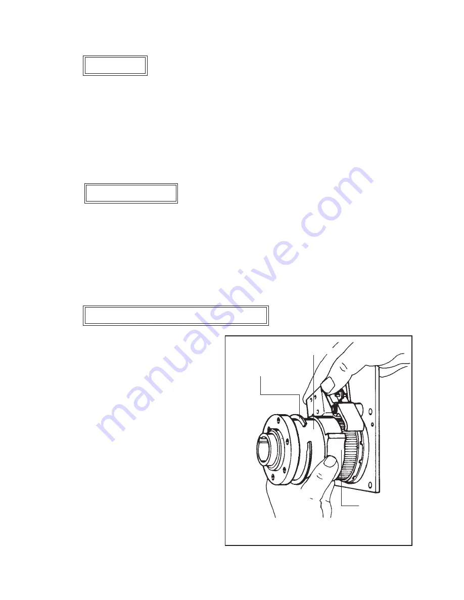
The stopping position of the head can be
changed if necessary by adjusting the position
of the stop cam on the control collar sleeve.
Turn the machine manually until the driver is
in the desired stopping position, the proceed as
follows:
Work the Retaining Ring out of its groove
and slide it forward on the Drive Sleeve.
Slide the cam of the Control Collar Assembly
(850888) off of the splines, rotate to align the
collar stop with the actuator and slide the cam
back on the splines. The actuator pawl will
have to be held clear during this operation.
Slide the retaining ring back into its groove.
Make sure brake is locked up before
proceeding, to insure the proper stop point.
Lubrication
Coil Replacement
Control Collar Adjustment (Figure 13)
Place the spring onto the plunger with the narrow end towards the actuator. Slide the solenoid onto
the actuator and plate assembly. Assemble the solenoid to the plate assembly with the cap screws and
washers.
Do not tighten
more than finger tight.
Energize the coil and adjust the gap between the actuator and the top of the collar stop to 0.015" to
0.030" by sliding the solenoid assembly. Note: push the collar toward the actuator to allow for
collar movement. Tighten the cap screws.
Figure 13 - Control Collar Adjustment
Retaining Ring
Drive Sleeve
Stop Cam
23
Summary of Contents for M27 Series
Page 2: ......
Page 3: ......
Page 26: ...24 Wiring Diagram Complete Wiring with Detail...
Page 27: ...25 Wiring Diagram AST 115V Models BST 230V Models...
Page 34: ...32 The M27 Stitcher Machine...
Page 35: ...33...
Page 42: ...NOTES 40...
Page 43: ......
Page 44: ...DBSM27 0415...


