10
The quality and quantity of work that can be stitched on the M27 is dependent upon the operator
making the necessary operating adjustments as accurately as possible. The following information
and instructions are provided so that the operator will clearly understand how to make the required
operating adjustments.
Additional Operator’s Manuals for the stitcher heads supported by the M27 Stitcher are included
with the Stitcher itself. Please refer to these manuals for specific instruction and operating adjustments
for the individual stitcher heads.
Operating Adjustments
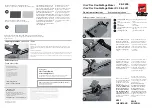
Adjusting for Thickness of Work (Figure 4)
Failure to properly adjust for the compression
will severely damage the stitcher.
WARNING
!
Figure 4 - Adjusting for Work Thickness
G30128 -
HAND WHEEL
G30158
G30099
G30119 -
THICKNESS GAUGE
G30103 (2)
Unlock the Hand Wheel (G30128)
by turning the Adjuster Crank Lock
(G30158) on the Adjuster Crank Housing
(G30099B) counter-clockwise. Turn the
Hand Wheel clockwise until the Adjuster
Spool (G30119) is raised sufficiently to
allow a sample of work to be inserted
between it and the lower Adjuster Stop
(G30103). The thickness gauge is locat-
ed on the right-hand side of the machine
if you are looking from the front of the
stitcher. With the work held flat in a
horizontal position, turn the Hand Wheel
counter-clockwise until the work is firm-
ly clamped between the Adjuster Spool
and the lower Adjuster Stop. Turn the
Hand Wheel back clockwise just enough
to allow the work to be withdrawn from
the Adjuster Spool, then return the Hand
Wheel to the setting at which the work
was clamped.
MEASURE HERE
Summary of Contents for M27 Series
Page 2: ......
Page 3: ......
Page 26: ...24 Wiring Diagram Complete Wiring with Detail...
Page 27: ...25 Wiring Diagram AST 115V Models BST 230V Models...
Page 34: ...32 The M27 Stitcher Machine...
Page 35: ...33...
Page 42: ...NOTES 40...
Page 43: ......
Page 44: ...DBSM27 0415...