T P 7 0 P Q u i c k St a r t
2.2.4
Setting Parameteres in a Delta VFD-M Series AC Motor Drive
Parameter
Setting
Description
P00
03
A master frequency is determined by an RS-485 port.
P01 01
Operation is controlled by external terminals. STOP on a keypad is
effective.
P03
60
Maximum operating frequency (50.00~400.0 Hz)
P08
1.50
Minimum output frequency (0.10~20.00 Hz)
P88
01
The communication address of the VFD-M series AC motor drive is 1.
P89
01
Baud rate: 9600 bps
P92 01
MODBUS ASCII mode
Data format: <7, E, 1>
※
If an AC motor dirve can not operate normally due to the fact that parameters are not set correctly,
users can set P76 to 10 (restore all parameters to the default value 60 Hz), and then set other
parameters according to the table above.
2.3
Example
After users install, wire and power up hardware, they can prepare to write programs. In order to make the users
have a specific target and a specific direction before they begin to write programs, the manual provides a
common example for the users. The complete procedure which starts with the creation of a new project and
ends with the downloading of the project to a PLC is described step by step.
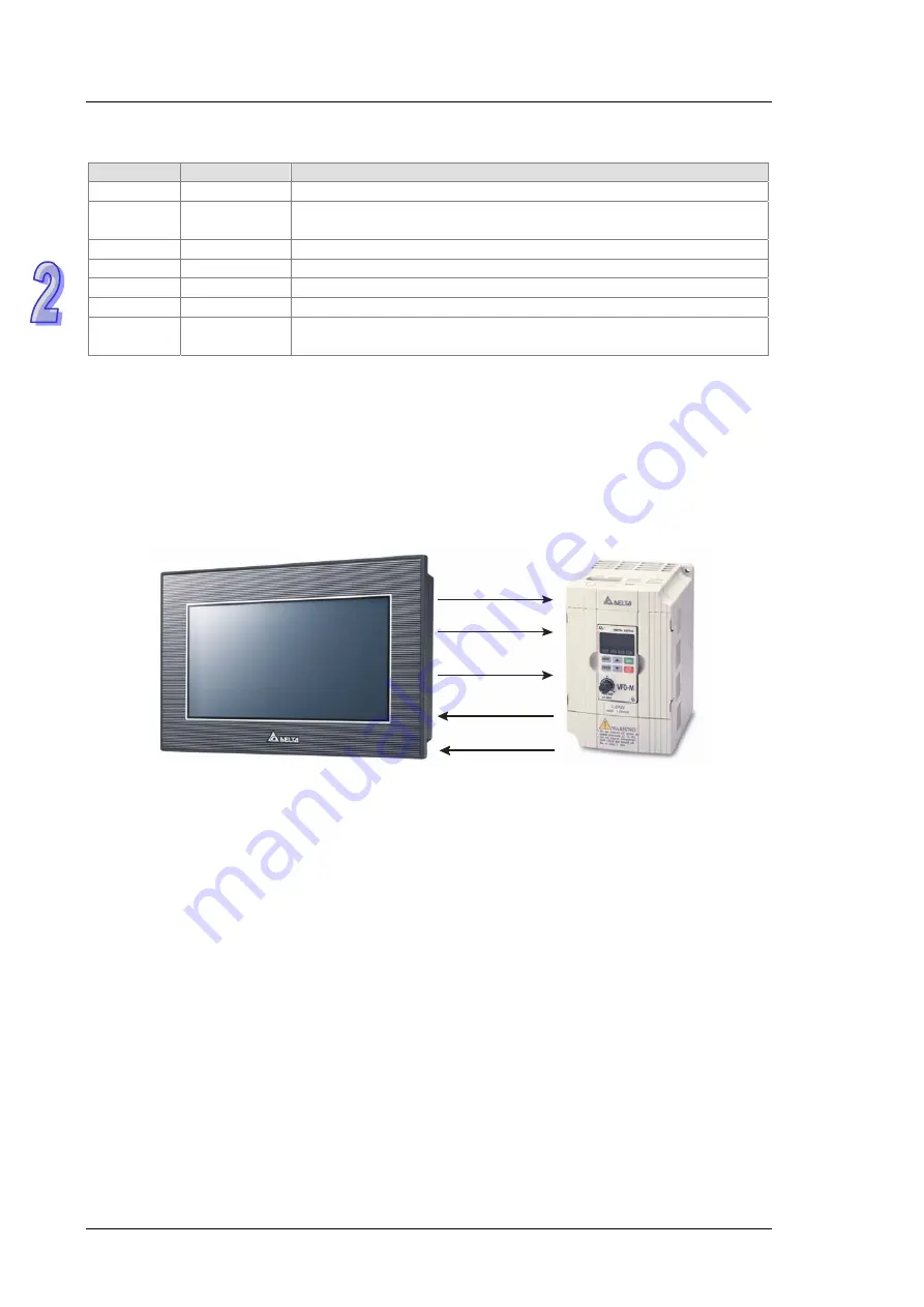
Structure of a system
Start ( Y0)
Stop (Y 1)
Rotational speed
comm and ( COM 3)
Curr ent r otational
speed ( COM3)
Alarm( COM3)
Control
The communication between a PLC and a Delta VFD-M series AC motor drive is described here. Y
devices on TP70P are used to control the forward/backward rotation of the AC motor drive. RS-485
communication (COM3) is used to read/set the frequency of signals output by the VFD-M series AC motor
drive. If the AC motor drive breaks down, an alarm signal in the AC motor dirve will be sent to TP70P.
Actions:
1. If the AC motor drive rotates forwards, its forward rotation indicator will be on, and the input which makes
the the AC motor drive rotate barckwards will be ineffective.
2. If the AC motor drive rotates backwards, its backward rotation indicator will be on, and the input which
makes the the AC motor drive rotate forwards will be ineffective.
3. If stop control is input, the operation of the AC motor drive will stop, and its stop indicator will be on.
4. The users can input a frequency range. The frequency range that the users set should be between the
maximum operaring frequency of the AC motor drive and the minimum operaring frequency of the AC
motor drive.
5. If the AC motor drive sends an error code, the operation of the AC motor drive will stop.
I/O devices in the PLC:
1. Forward rotation control (M0)
2. Backward rotation control (M1)
3. Stop control (M2)
4. Forward rotation switch (Y0)
2 - 4


