English-
30
Pr.
Explanation
Settings
Factory
Setting
NOTE
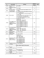
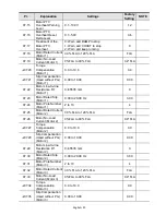
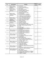
12.18
Max. ACI3 Input
Current
0.0 to 20.0mA
20.0
12.19
Max. ACI3 Scale
Percentage
0.0 to 100.0%
100.0
12.20
AO1 Terminal
Analog Signal Mode
0: AVO1
1: ACO1 (analog current 0.0 to 20.0mA)
2: ACO1 (analog current 4.0 to 20.0mA)
0
0: Analog Frequency
12.21
AO1 Analog Output
Signal
1: Analog Current (0 to 250% rated current)
0
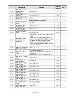
12.22
AO1 Analog Output
Gain
1 to 200%
100
0: AVO2
1: ACO2 (analog current 0.0 to 20.0mA)
12.23
AO2 Terminal
Analog Signal Mode
2: ACO2 (analog current 4.0 to 20.0mA)
0
0: Analog Frequency
12.24
AO2 Analog Output
Signal
1: Analog Current (0 to 250% rated current)
0
12.25
AO2 Analog Output
Gain
1 to 200%
100
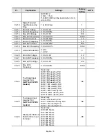
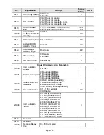
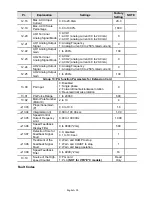
Group 13: PG function Parameters for Extension Card
13.00 PG
Input
0: Disabled
1: Single phase
2: Forward/Counterclockwise rotation
3: Reverse/Clockwise rotation
0
13.01
PG Pulse Range
1 to 20000
600
13.02
Motor Pole Number
(Motor 0)
2 to 10
4
a
13.03
Proportional Gain
(P)
0.0 to 10.0
1.0
a
13.04
Integral Gain (I)
0.00 to 100.00 sec
1.00
a
13.05
Speed Control
Output Frequency
Limit
0.00 to 100.00Hz
10.00
a
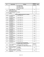
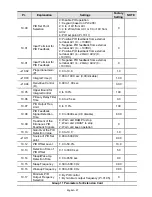
13.06
Speed Feedback
Display Filter
0 to 9999 (*2ms)
500
a
13.07
Detection Time for
Feedback Signal
Fault
0.0: disabled
0.1 to 10.0 sec
1
0: Warn and RAMP to stop
1: Warn and COAST to stop
a
13.08
Treatment of the
Feedback Signal
Fault
2: Warn and keep operation
1
a
13.09
Speed Feedback
Filter
0 to 9999 (*2ms)
16
0: PG card
13.10
Source of the High-
speed Counter
1: PLC
(NOT for VFD*E*C models)
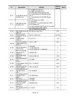
Read
Only
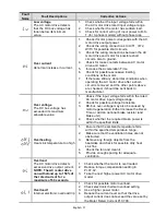
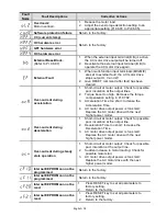
Fault Codes


