14
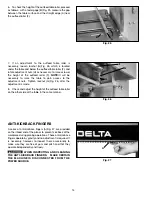
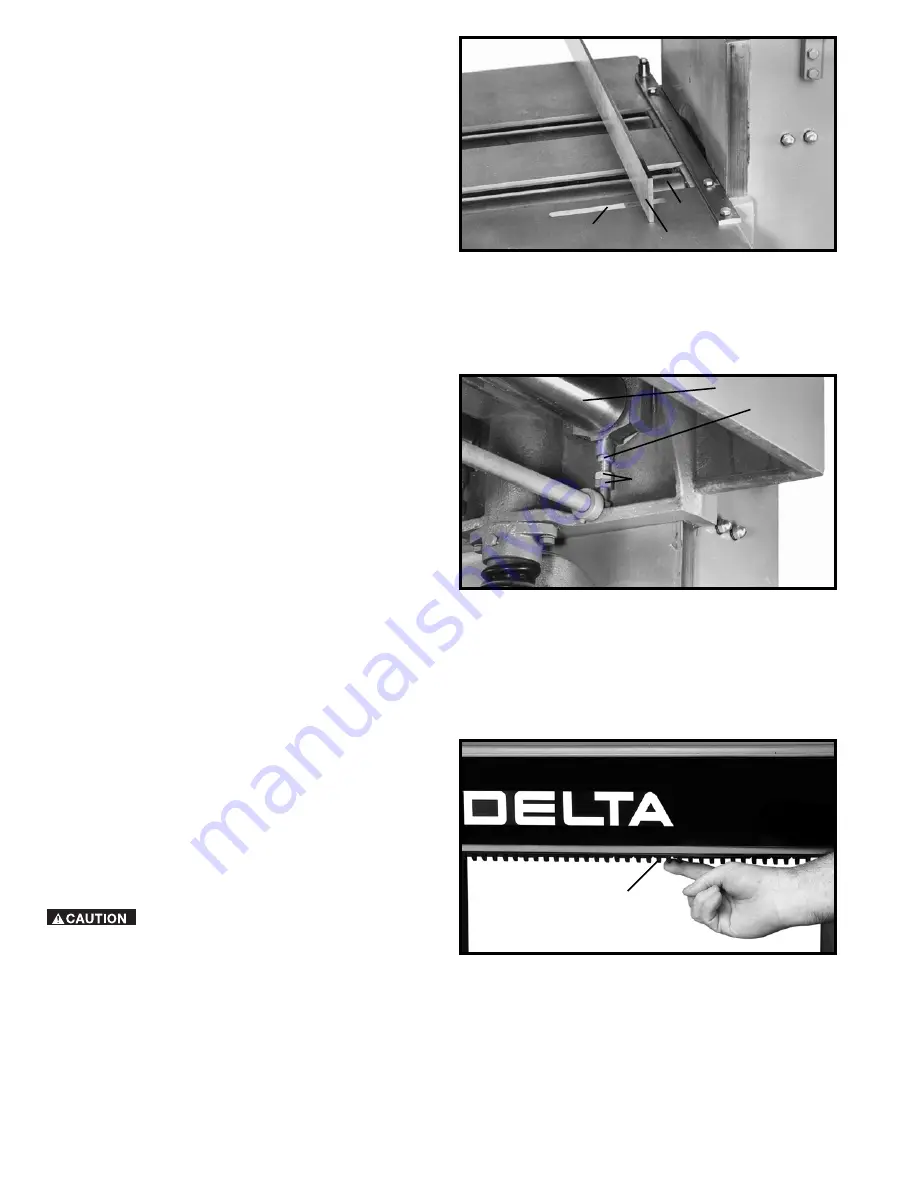
Fig. 25
6.
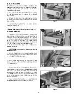
To check the height of the outfeed table roller, proceed
as follows: with a feeler gage (B) Fig. 25, measure the gap
between the table surface and the straight edge (A) near
the outfeed roller (F).
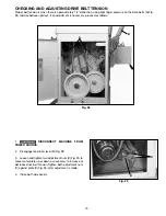
Fig. 26
7.
If an adjustment to the outfeed table roller is
necessary, loosen locknut (G) Fig. 26, which is located
under the table and below the outfeed table roller (F), and
rotate adjustment nuts (H) as necessary, to raise or lower
the height of the outfeed roller (F).
NOTE:
It will be
necessary to raise the table to gain access to the
adjustment nuts. Tighten locknut (G) Fig. 26, after the
adjustment is made.
8.
Check and adjust the height of the outfeed table roller
on the other side of the table in the same manner.
ANTI-KICKBACK FINGERS
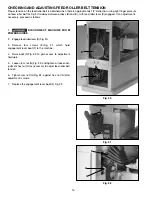
A series of anti-kickback fingers (A) Fig. 27, are provided
on the infeed end of the planer to prevent kickback of the
workpiece during planing operations. These anti-kickback
fingers operate by gravity and no adjustment is required. It
is necessary, however, to inspect them occasionally to
make sure they are free of gum and pitch and that they
operate independently and freely.
WHEN INSPECTING AND CLEANING
THE ANTI-KICKBACK FINGERS, MAKE CERTAIN
THE MACHINE IS DISCONNECTED FROM THE
POWER SOURCE.
Fig. 27
B
A
F
F
G
H
A


