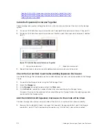
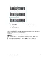


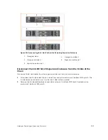


Figure 71. Remove the A-Side Cable from the Storage Controllers
1.
Storage system
2. Storage controller 1
3. Storage controller 2
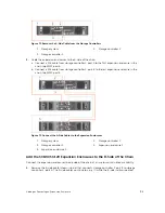
2.
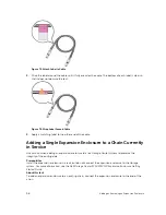
Cable the expansion enclosures to the A-side of the chain.
a. Connect a SAS cable from storage controller 1: port A to the first expansion enclosure in the
chain, top EMM, port A.
b. Connect a SAS cable from storage controller 2: port B to the last expansion enclosure in the
chain, top EMM, port B.
Figure 72. Connect the A-Side Cables to the Expansion Enclosures
1.
Storage system
2. Storage controller 1
3. Storage controller 2
4. Expansion enclosure 1
5. Expansion enclosure 2
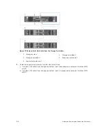
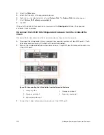
Add the SC100/SC120 Expansion Enclosures to the B-Side of the Chain
Connect the expansion enclosures to one side of the chain at a time to maintain drive availability.
1.
Remove the B-side cable (shown in blue) that connects storage controller 1: port B to storage
controller 2: port A. The A-side cables continue to carry IO while the B-side is disconnected.
Adding or Removing an Expansion Enclosure
95