background image

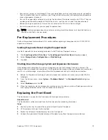
• Remove any jewelry or metal objects from your body because they are excellent metal conductors 

that can create short circuits and harm you if they come into contact with printed circuit boards or 

areas where power is present.

• Do not lift a expansion enclosure chassis by the handles of the power supply units (PSUs). They are 

not designed to hold the weight of the entire chassis, and the chassis cover may become bent.

• Before moving a expansion enclosure chassis, remove the PSUs to minimize weight.
• Do not remove drives until you are ready to replace them.

NOTE: To ensure proper expansion enclosure cooling, hard drive blanks must be installed in any 
hard drive slot that is not occupied.

Pre-Replacement Procedures

Perform the procedures described in this section before replacing a component of an SC100/SC120 

expansion enclosure.

Sending Diagnostic Data Using Dell SupportAssist

Use Dell SupportAssist to send diagnostic data to Dell Technical Support Services.

1.

Click 

Send SupportAssist Data Now

. The 

Send Support Assist Data Now

 dialog box appears.

2.

Select 

Storage Center Configuration

 and 

Detailed Logs

.

3.

Click 

OK

.

Shutting Down the Storage System and Expansion Enclosures

If the replacement component is not hot-swappable, use the Dell Storage Client to shut down the 

storage system and expansion enclosures. Shutting down the storage system and expansion enclosures 

results in a system outage, so plan to perform these procedures during a maintenance window.

1.

Before shutting down the storage system and expansion enclosures, make sure you identify the 

failed part.

2.

From the Actions menu, select 

System


Shutdown/Restart

. The 

Shutdown/Restart

 dialog box 

appears.

3.

Select 

Shutdown

 and click 

OK

.

4.

When the storage system and expansion enclosures are shut down, switch off both power switches 

and unplug the power cables from the expansion enclosure.

Replacing the Front Bezel

The front bezel is a cover for the front panel of the expansion enclosure.

About this task

The front bezel must be removed from the front panel when replacing hard drives.

Steps
1.

Use the system key to unlock the keylock at the left end of the bezel.

2.

Lift the release latch next to the keylock.

3.

Rotate the left end of the bezel away from the front panel.

4.

Unhook the right end of the bezel and pull the bezel away from the expansion enclosure.

Replacing SC100/SC120 Components

13

Summary of Contents for Storage Center sc100

Page 1: ...Dell Storage Center SC100 and SC120 Expansion Enclosure Owner s Manual Regulatory Model E03J E04J Regulatory Type E03J001 E04J001 ...

Page 2: ...problem WARNING A WARNING indicates a potential for property damage personal injury or death Copyright 2015 Dell Inc All rights reserved This product is protected by U S and international copyright and intellectual property laws Dell and the Dell logo are trademarks of Dell Inc in the United States and or other jurisdictions All other marks and names mentioned herein may be trademarks of their res...

Page 3: ...arge Precautions 12 General Safety Precautions 12 Pre Replacement Procedures 13 Sending Diagnostic Data Using Dell SupportAssist 13 Shutting Down the Storage System and Expansion Enclosures 13 Replacing the Front Bezel 13 Replacing Power Supply Cooling Fan Modules 14 Identifying the Failed Power Supply 14 Identifying the Failed Cooling Fan 16 Replacing a Power Supply Cooling Fan Module 17 Replacin...

Page 4: ...27 Troubleshooting Power Supply Cooling Fan Modules 27 Troubleshooting Hard Drives 27 Troubleshooting Enclosure Management Modules 28 Troubleshooting the Control Panel 28 4 SC100 SC120 Technical Specifications 29 Technical Specifications 29 4 ...

Page 5: ...lated Publications The following documentation is available for the SC100 SC120 expansion enclosure Dell Storage Center SC100 and SC120 Expansion Enclosure Getting Started Guide Provides information about an SC100 SC120 expansion enclosure such as installation instructions and technical specifications Dell Storage Center SCv2000 Series Virtual Media Update Instructions Describes how to install Sto...

Page 6: ... for individual cmdlets is available online Dell Storage Client Administrator s Guide Provides information about the Dell Storage Client and how it can be used to manage a Storage Center Dell Enterprise Manager Administrator s Guide Contains in depth feature configuration and usage information Dell TechCenter Provides technical white papers best practice guides and frequently asked questions about...

Page 7: ...ndant power supply cooling fan modules and two redundant enclosure management modules EMMs SC100 SC120 Expansion Enclosure Monitoring and Diagnostics The Storage Center OS generates alert messages for temperature I O module fan module disk and power conditions for Storage Center components Use the Dell Storage Client to view these alerts The SC100 SC120 also has LED indicators to notify you of a p...

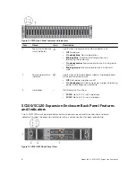
Page 8: ...hts when at least one power supply is supplying power to the expansion enclosure Off Both power supplies are off On steady green At least one power supply is providing power to the expansion enclosure 3 Hard drives Dell Enterprise Plus Drives SC100 Up to 12 3 5 inch hard drives SC120 Up to 24 2 5 inch hard drives SC100 SC120 Expansion Enclosure Back Panel Features and Indicators The SC100 SC120 ba...

Page 9: ...n modules 2 Contains a 700 W power supply and fans that provide cooling for the expansion enclosure 7 Enclosure Management Modules 2 EMMs provide the data path and management functions for the expansion enclosure SC100 SC120 Expansion Enclosure EMM Features and Indicators The SC100 SC120 includes two Enclosure Management Modules EMMs in two interface slots Figure 4 SC100 SC120 EMM Features and Ind...

Page 10: ... amber five times per sequence Firmware versions are different between the two EMMs SC100 SC120 Expansion Enclosure Drives Dell Enterprise hard disk drives HDDs and Enterprise Solid State Drives eSSDs are the only drives that can be installed in SC100 SC120 expansion enclosures If a non Dell Enterprise drive is installed Storage Center prevents the drive from being managed The drives in an SC100 e...

Page 11: ...y precautions Dell recommends that only individuals with rack mounting experience install an SC100 SC120 expansion enclosure in a rack Make sure the expansion enclosure is fully grounded at all times to prevent damage from electrostatic discharge When handling the expansion enclosure hardware you should use an electrostatic wrist guard not included or a similar form of protection The expansion enc...

Page 12: ...hin 24 hours Unplug the storage system chassis before you move it or if you think it has become damaged in any way When powered by multiple AC sources disconnect all supply power for complete isolation Electrostatic Discharge Precautions Always follow electrostatic discharge ESD precautions to avoid injury and damage to Storage Center equipment Electrostatic discharge ESD is generated by two objec...

Page 13: ...figuration and Detailed Logs 3 Click OK Shutting Down the Storage System and Expansion Enclosures If the replacement component is not hot swappable use the Dell Storage Client to shut down the storage system and expansion enclosures Shutting down the storage system and expansion enclosures results in a system outage so plan to perform these procedures during a maintenance window 1 Before shutting ...

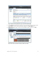
Page 14: ...laced separately If one module fails the second module continues to provide power to the expansion enclosure NOTE When a power supply cooling fan module fails the fan speed in the remaining module increases significantly to provide adequate cooling The fan speed decreases gradually when a new power supply cooling fan module is installed Identifying the Failed Power Supply To determine which power ...

Page 15: ...tified in the previous step and select Power Supplies The status of each power supply is displayed in the Power Supplies tab 6 Select the failed power supply The location of the failed power supply is displayed in the Power Supply View tab Figure 8 Rear View of the Enclosure Showing the Failed Power Supply Replacing SC100 SC120 Components 15 ...

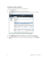
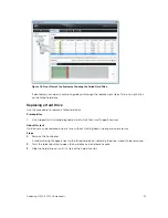
Page 16: ...es the enclosure with the failed cooling fan Figure 9 Hardware Alert Identifying the Enclosure with the Failed Cooling Fan 4 In the Hardware tab navigation pane expand the enclosure identified in the previous step 5 Select Cooling Fan Sensors The status of each cooling fan is displayed in the Cooling Fans tab 6 Select the failed cooling fan The location of the failed cooling fan is displayed in th...

Page 17: ...at a time without shutting down the expansion enclosure Steps 1 Press the power switch on the power supply cooling fan module to turn it off 2 Remove the hook and loop strap that secures the power cable and disconnect the power cable from the power supply cooling fan module 3 Push the release tab on the power supply cooling fan module to the right and slide it out of the chassis using the handle C...

Page 18: ...witch 4 Slide the replacement power supply cooling fan module into the chassis until it is fully seated and the release tab clicks into place 5 Connect the power cable to the power supply cooling fan module and make sure the cable is plugged into a power outlet 6 Secure the power cable using the hook and loop strap 18 Replacing SC100 SC120 Components ...

Page 19: ...sures support hot swappable hard drives The SC100 expansion enclosure supports up to 12 3 5 inch hard drives installed in a four column three row configuration The SC120 expansion enclosure supports up to 24 2 5 inch hard drives installed vertically side by side Hard drives are connected to a backplane through hard drive carriers Hard drive blanks are installed in the hard drive bays that are not ...

Page 20: ...nter 3 In the Hardware Alerts area find the hardware alert that identifies the enclosure with the failed hard drive Figure 15 Hardware Alert Identifying the Enclosure with the Failed Hard Drive 4 In the Hardware tab navigation pane expand the enclosure identified in the previous step 5 Select Disks The status of each hard drive is displayed in the Disks tab 6 Select the failed hard drive The locat...

Page 21: ...SupportAssist to send diagnostic data to Dell Technical Support Services About this task Hard drives can be replaced one at a time without shutting down the expansion enclosure Steps 1 Remove the front bezel A solid amber light appears next to the failed hard drive indicating the drive is ready to be removed 2 Press the release button to open the hard drive carrier release handle 3 Slide the hard ...

Page 22: ...recognize the hard drive and determine its status When functioning properly the hard drive s status indicator turns green In addition the hard drive indicator turns green in the Dell Storage Client 7 Replace the front bezel 8 In the Dell Storage Client make sure that the replacement hard drive is recognized and shown as up and running If the Dell Storage Client informs you that there are unassigne...

Page 23: ...with a drive or drive blank Replacing an Enclosure Management Module The SC100 SC120 expansion enclosures support redundant hot swappable Enclosure Management Modules EMMs EMMs provide the following data path and enclosure management functions for the expansion enclosure Monitoring and controlling expansion enclosure environment elements such as temperature fan power supplies and expansion enclosu...

Page 24: ... each EMM is displayed in the I O Modules tab 6 Select the failed EMM to the display its location in the I O Module View tab Figure 20 Rear View of the Enclosure Showing the Failed EMM Replacing an Enclosure Management Module Use this procedure to replace a failed EMMs Prerequisites 1 Use SupportAssist to send diagnostic data to Dell Technical Support Services 24 Replacing SC100 SC120 Components ...

Page 25: ...ver 3 Release tab 4 Insert the replacement EMM into the bay until it is fully seated 5 Push the release lever toward the chassis until it clicks into place 6 Reconnect the SAS cables to the EMM Next steps 1 Use SupportAssist to send diagnostic data to Dell Technical Support Services Replacing Rack Rails Rack rails are used to install SC100 SC120 expansion enclosures into a rack Prerequisites 1 Use...

Page 26: ...and expansion enclosures were previously shut down perform this procedure to start them up 1 Plug the power cables into the power supply cooling fan modules of the storage system and expansion enclosures 2 Turn on each expansion enclosure by pressing the power switches on the power supply cooling fan modules NOTE Always turn on the expansion enclosures before turning on the storage systems 3 Turn ...

Page 27: ...fferent power source Replace the power cord If the DC power LED is not lit verify that the power switch is turned on 3 Reseat the power supply cooling fan module by removing and reinstalling it NOTE Allow several seconds for the expansion enclosure to recognize the power supply cooling fan module and determine its status Troubleshooting Hard Drives Use these steps to troubleshoot hard drives 1 Che...

Page 28: ...s on the expansion enclosure and the storage system c Restart the expansion enclosure and then the storage system d Recheck the link status LEDs If the link status LEDs are not green replace the cables Troubleshooting the Control Panel Use these steps to troubleshoot the control panel 1 Determine the status of the control panel LEDs If the LEDs are not lit and the enclosure is powered on the contr...

Page 29: ...ty Configurations Storage Center supports up to 168 drives in one redundant path SAS chain An SCv2000 supports up to 13 SC100 expansion enclosures or 6 SC120 expansion enclosures An SCv2020 supports up to 12 SC100 expansion enclosures or 6 SC120 expansion enclosures Redundant Array of Independent Disks RAID Storage System SCv2000 SCv2020 Management RAID management using Dell Storage Client2015 R1 ...

Page 30: ...Three LED status indicators for power supply status power supply cooling fan fault status and AC status Power Supplies AC power supply per power supply Wattage 700 W Voltage 100 240 VAC 8 6 4 3 A Heat dissipation SC100 191 147 W SC120 133 114 W Maximum inrush current Under typical line conditions and over the entire system ambient operating range the inrush current may reach 55 A per power supply ...

Page 31: ...e maximum operating temperature is derated 1 F per 550 ft Storage 40 to 65 C 40 to 149 F with a maximum temperature gradation of 20 C per hour Relative humidity Operating 20 to 80 noncondensing with a maximum humidity gradation of 10 per hour Storage 5 to 95 noncondensing Maximum vibration Operating 0 26 G at 5 350 Hz for 15 min Storage 1 88 G at 10 500 Hz for 15 min Maximum shock Operating Half s...

Page 32: ...es above 2950 feet the maximum operating temperature is derated 1 F per 550 ft Storage 16 to 10 600 m 50 to 35 000 ft Airborne Contaminant Level Class G2 or lower as defined by ISA S71 04 1985 32 SC100 SC120 Technical Specifications ...

Reviews: