background image

TERA1x00 PC-over-IP Administrative Interface User Manual


TER0606004 Issue 3


© 2008 Teradici Corporation 

Page 49 of 111


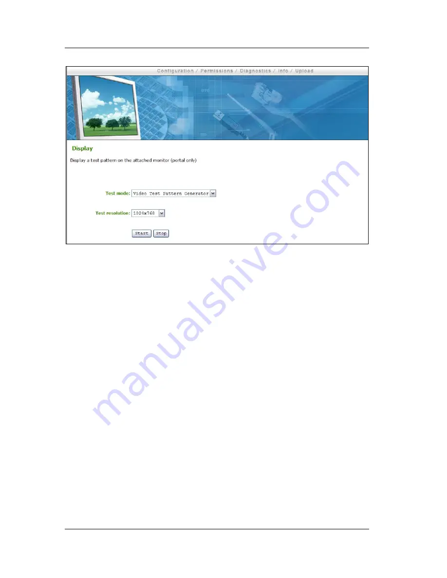
Figure 29: Display Webpage 


1.7.6.1 Test mode 

The 

Test Mode

 pull-down menu allows enabling a test pattern on the attached 

monitor(s).  The test pattern options are 

  Video Test Pattern Generator 

  Pseudo Random Bitstream 


This option is only available on a Portal; on the Host it is disabled and non-editable.   

1.7.6.2 Test resolution 

The 

Test resolution

 pull-down menu sets the test pattern resolution.  The options 

are: 

 1024x768 

 1280x1024 

 1600x1200 

 1920x1200 


This option is only available on a Portal; on the Host it is disabled and non-editable.   

1.7.6.3 Start/Stop 

The 

Start

 button starts the test pattern, while the 

Stop

 button stops the test pattern. 

This option is only available on a Portal; on the Host it is disabled and non-editable.   

Summary of Contents for Precision R5400

Page 1: ...P Administrative Interface User Manual May 26 2008 Revision 3 Teradici Corporation 500 4400 Dominion St Burnaby BC Canada V5G 4G3 Abstract This document describes administration interfaces of the PC over IPTM Firmware for the TERA1100 and TERA1200 processors ...

Page 2: ...onfiguration see Section 1 5 5 2 Updated RDP web configuration see Section 1 5 6 Added Maximum Initial Image Quality to Image web configuration see Section 1 5 9 2 Added Time web configuration see Section 1 5 11 Added Firmware Part Number in Version web information see Section 1 8 1 1 Updated Firmware Upload build filename web information see Section 1 9 1 1 Updated RDP OSD configuration see Secti...

Page 3: ...ver IP Half Duplex in compatibility Section 1 5 1 7 Clarified when Device Bandwidth Limit and Device Bandwidth Target are applied Section 1 5 5 Updated USB Permissions documentation for USB authorization unauthorization functionality Section 1 6 1 Added USB devices status descriptions in Attached Devices USB Devices Section 1 8 2 2 ...

Page 4: ...curity 15 1 3 1 CA Root Certificate Installation 15 1 4 Log In 15 1 4 1 Warning 16 1 4 2 Password 16 1 4 3 Idle Timeout 16 1 5 Configuration 16 1 5 1 Network 17 1 5 2 Connection Management 20 1 5 3 Discovery 22 1 5 4 Session 23 1 5 5 Bandwidth 26 1 5 6 RDP 28 1 5 7 Language 29 1 5 8 OSD 30 1 5 9 Image 31 1 5 10 Monitor Emulation 33 1 5 11 Time 33 1 5 12 Password 35 1 5 13 Reset Parameters 36 1 6 P...

Page 5: ...Logo 55 2 On Screen Display OSD 57 2 1 Connect Screen 57 2 1 1 Connect Button 58 2 2 OSD Options Menu 58 2 3 Configuration 59 2 3 1 Network 60 2 3 2 Connection Management 62 2 3 3 Discovery 64 2 3 4 Session 65 2 3 5 Bandwidth 66 2 3 6 RDP 67 2 3 7 Language 68 2 3 8 OSD 69 2 3 9 Reset 70 2 4 Diagnostics 71 2 4 1 Event Log 71 2 4 2 Session Statistics 72 2 4 3 PCoIP Processor 74 2 4 4 Ping 74 2 5 Inf...

Page 6: ...d Enable Host Discovery Example 88 4 2 1 Portal DHCP and Discovery Configuration 88 4 2 2 Host DHCP and Discovery Configuration 91 4 2 3 Initiating DHCP Discovery Session 94 4 3 Bandwidth and Image Configuration Example 95 4 3 1 Configuring Host Bandwidth Limit to 25 Mbps 96 4 3 2 Configuring Image Properties 98 4 3 3 Configuring Host Bandwidth Limit to 0 Mbps no limit 100 4 4 USB Permissions Exam...

Page 7: ... Language Configuration Webpage 30 Figure 13 OSD Configuration Webpage 31 Figure 14 Image Configuration Webpage 32 Figure 15 Monitor Emulation Configuration Webpage 33 Figure 16 Time Configuration Webpage 34 Figure 17 Password Configuration Webpage 35 Figure 18 Reset Parameters Webpage 36 Figure 19 Permissions Menu Navigation 37 Figure 20 USB Permissions Webpage 38 Figure 21 Audio Permissions Webp...

Page 8: ... 70 Figure 49 Reset 71 Figure 50 Event Log 72 Figure 51 Session Statistics 73 Figure 52 PCoIP Processor 74 Figure 53 Ping 75 Figure 54 Version 76 Figure 55 Mouse 77 Figure 56 Keyboard 78 Figure 57 Image 79 Figure 58 Change Password 80 Figure 59 Network Connection Lost Overlay 81 Figure 60 USB Device Not Authorized Overlay 81 Figure 61 Portal Connection Management Peer to Peer Configuration 83 Figu...

Page 9: ...on 25 Mbps 97 Figure 79 Simplified User Bandwidth Requirements 25 Mbps 98 Figure 80 Portal Minimum Image Quality Configuration 99 Figure 81 Host Bandwidth Limit Configuration 0 Mbps no limit 101 Figure 82 Simplified User Bandwidth Requirements no limit 102 Figure 83 USB Permissions Example Add new Button 102 Figure 84 USB Permissions Example Selecting the Class Entry Type 103 Figure 85 USB Permiss...

Page 10: ...s 38 Table 5 USB Device Unauthorization Entry Types 39 Table 6 VPD Information 52 Table 7 Firmware Information 52 Table 8 VPD Information 52 Table 9 USB Device Status 53 Table 10 Connection Manager Method 63 Table 11 Peer Identity Methods 65 Table 12 VPD Information 76 Table 13 Firmware Information 76 Table 14 Firmware Information 77 Table 15 TERA1100 Supported Languages 108 Table 16 TERA1100 Supp...

Page 11: ...ame GPU Graphics Processing Unit GUI Graphical User Interface presented by the Portal On Screen Display when not operating in a PC over IP session HPDET Hot Plug Detect MTU Maximum Transmission Unit NTP Network Time Protocol OS Operating System OSD On Screen Display PC over IPTM Personal Computer over Internet Protocol PC over IP Host Host side of PC over IP system PC over IP Portal Portal or desk...

Page 12: ... the learning curve Additionally the web interface and OSD are organized as similarly as possible to reduce the total user learning curve This document describes the user PC over IP Host and Portal user interfaces Where applicable it is stated when the feature is only available for the Host i e host only or Portal i e desktop side only This document has three main sections Section 1 details the PC...

Page 13: ...nistration Web interface PCoIP Processor Displays PC over IP processor information TERA1100 Portal PCoIPTM Processor TERA1200 Host PCoIPTM Processor Drop down menus The five menus are Configuration Permissions Diagnostics Info and Upload Webpage information Title and summary Data field Editable and or displayed parameters inline help is displayed when appropriate Apply Cancel Each webpage with edi...

Page 14: ...on the TERA1x00 devices has been tested and is compatible with the following web browsers Firefox 1 5 and 2 0 Internet Explorer 6 0 and 7 0 Other browsers may also be compatible 1 2 Administrative Web Interface IP Address To access the Administrative Web Interface the administrator must browse to the IP address of the TERA1x00 The IP address used depends on the method that IP addresses are determi...

Page 15: ...talled in the internet browser to avoid the browser security warnings Steps for installing the certificate on Internet Explorer 7 and Firefox are detailed below Internet Explorer 7 1 Open the Tools menu and select Internet Options 2 On the Content tab and select Certificates 3 On the Trusted Root Certification Authorities tab select Import 4 Follow the directions to import the certificate ensure t...

Page 16: ...into a session will terminate any other administration session in progress 1 4 2 Password The Password field allows entering the password to gain access to the administration webpage The default value is blank i e Information concerning changing the password can be found in Section 1 5 12 1 4 3 Idle Timeout The Idle Timeout field sets the administration idle timeout The options are 1 minute 5 minu...

Page 17: ...covery Session Bandwidth RDP Language OSD Image Monitor Emulation Time Password Reset Parameters Figure 3 Configuration Menu Navigation 1 5 1 Network The Network webpage allows an administrator to set the Portal and Host network parameters Note The Portal Network parameters can also be configured using the Portal OSD See Section 2 3 1 Network ...

Page 18: ...is field is required If DHCP is enabled this field is not editable This field must be a valid IP address and if an invalid IP address is entered the web interface will prompt the administrator to correct it 1 5 1 3 Subnet Mask The Subnet Mask is the device s subnet mask If DHCP is disabled this field is required If DHCP is enabled this field is not editable This field must be a valid IP address an...

Page 19: ...N instead of an IP address see Section 1 5 2 2 This field must be a valid IP address and if an invalid IP address is entered the web interface will prompt the administrator to correct it 1 5 1 7 Ethernet Mode The Ethernet Mode field configures the Ethernet mode of the Portal The options are Auto 10 Mbps Full Duplex 100 Mbps Full Duplex This option is only available on a Portal on the Host it is di...

Page 20: ...ternal Connection Manager Server communicates with and can remotely control and configure the device Additionally the connection manager can locate an appropriate peer for the device to connect to and initiate the connection Connection management can greatly simplify the administration effort for a large complex system Note The Portal Connection Management parameters can also be configured using t...

Page 21: ...ager is identified by IP address or by Fully Qualified Domain Name FQDN If connection management is disabled this field is not required and is not editable Table 1 shows the configuration parameters available when either method is chosen If an invalid IP address or DNS name is entered the web interface will prompt the administrator to correct it Table 1 Connection Manager Method Method Data Fields...

Page 22: ...meters can also be configured using the Portal OSD See Section 2 3 3 Discovery Figure 7 Discovery Configuration Webpage 1 5 3 1 SLP Discovery 1 5 3 1 1 Enable SLP Discovery When the Enable SLP Discovery option is enabled the Host and Portals can be dynamically discovered by SLP management entities without requiring prior knowledge of their locations in the network Using a discovery mechanism can d...

Page 23: ...s DNS SRV Resource Records without requiring prior knowledge of their locations in the network Using a discovery mechanism can dramatically reduce configuration and maintenance effort for complex systems This discovery mechanism is independent of SLP Discovery 1 5 3 2 2 DNS SRV Discovery Delay The DNS SRV Discovery Delay configures the delay after the final domain name variation for DHCP options 1...

Page 24: ...TERA1x00 PC over IP Administrative Interface User Manual TER0606004 Issue 3 2008 Teradici Corporation Page 24 of 111 Figure 8 Session Configuration Webpage ...

Page 25: ... on a Host on the Portal it is disabled and non editable 1 5 4 2 Session Type The Session Type option is only available on the Portal This option is disabled and non editable on the host device The user can choose PC over IP session or RDP session For information on the TERA1100 RDP client see Section 6 Appendix C TERA1100 RDP Compatibility This option is only available on a Portal on the Host it ...

Page 26: ...ver IP See Figure 8 Peer FQDN Peer DNS Name Used with Portal RDP client only See Figure 9 1 5 4 4 Enable Auto Reconnect The Enable Auto Reconnect option allows the Portal to automatically reconnect with the last connected Host after a power cycle This option is only available on a Portal on the Host it is disabled and non editable 1 5 4 5 Session Timeout The Session Timeout configures the timeout ...

Page 27: ...t all PC over IP sessions will require the maximum at all times A setting of 0 configures the PC over IP processor to adjust the bandwidth depending on network congestion If there is no congestion there will be no limit i e up to the maximum rate available It is recommended to set Device Bandwidth Limit to the limit of the network connected to the Portal and Host See Section 4 3 Bandwidth and Imag...

Page 28: ...P webpage allows configuration of the Remote Desktop Protocol RDP specific device settings For information on the TERA1100 RDP client see Section 6 Appendix C TERA1100 RDP Compatibility This option is only available on a Portal on the Host it is disabled and non editable Note The Portal RDP parameters can also be configured using the Portal OSD See Section 2 3 6 RDP Figure 11 RDP Configuration Web...

Page 29: ...ures where the audio playback occurs for the RDP session Possible options are Do not play Play on client Play on host 1 5 6 5 Enable Wallpaper The Enable Wallpaper field enables the use of wallpaper with the RDP session 1 5 6 6 Enable Themes The Enable Themes field enables the use of desktop themes with the RDP session 1 5 7 Language The Language webpage allows changing the user interface language...

Page 30: ...nguage and Keyboard Support for supported languages 1 5 7 2 Keyboard Layout The Keyboard Layout field allows the administrator to change the keyboard layout Refer to Table 16 in Section 5 Appendix B TERA1100 Portal Language and Keyboard Support for supported keyboard layouts 1 5 8 OSD The OSD webpage allows modifying the On Screen Display OSD parameters This option is only available on a Portal on...

Page 31: ...acters The screen saver is a simple black screen with the screen saver text jumping randomly 1 5 8 2 Screen Saver Timeout The Screen Saver Timeout field allows the configuring the screen saver timeout The timeout can be configured in seconds up to 9999 seconds A setting of 0 seconds disables the screen saver 1 5 9 Image The Image webpage allows adjusting image graphics quality of the PC over IP se...

Page 32: ...constrained environments When network bandwidth is not constrained the PCoIP system will maintain perception free quality regardless of the Minimum Image Quality setting The Minimum Image Quality must be set less than or equal to the Maximum Initial Image Quality Note The Minimum Image Quality can also be configured using the Portal OSD See Section 2 6 3 Image See Section 4 3 Bandwidth and Image C...

Page 33: ... and non editable Figure 15 Monitor Emulation Configuration Webpage 1 5 10 1Enable Monitor Emulation When Enable Monitor Emulation is disabled the Host will only respond to Display Data Channel DDC when in a PC over IP session When Enable Monitor Emulation is enabled the Host will use emulated data for DDC queries regardless if in a PC over IP session of not There are Enable Monitor Emulation fiel...

Page 34: ...Identify NTP Host By The Identify NTP Host by selector allows the administrator to choose whether the NTP Host is identified by IP address or by Fully Qualified Domain Name FQDN If NTP is disabled this field is not required and is not editable Table 3 shows the configuration parameters available when either method is chosen If an invalid IP address or DNS name is entered the web interface will pro...

Page 35: ...ute s Hour s Day s and Week s 1 5 11 6Time Zone The Time Zone field allows configuration for the local time zone 1 5 11 7Enable Daylight Savings Time The Enable Daylight Savings Time field allows enabling and disabling of daylight savings 1 5 12 Password The Password webpage allows updating the local administrative password for the device Note that this will affect the web interface and the local ...

Page 36: ...ndividually 1 5 12 3Confirm New Password The Confirm New Password field must match the New Password field for the change to take place 1 5 13 Reset Parameters The Reset webpage allows resetting all the configurable parameters stored in flash Note The Portal Reset Parameters can also be initiated using the Portal OSD See Section 2 3 9 Reset Figure 18 Reset Parameters Webpage 1 5 13 1Reset Parameter...

Page 37: ...s specifying authorized and unauthorized USB devices The USB webpage is divided into two sections Authorized Devices white list and Unauthorized Devices black list Entries can define an authorized or unauthorized device or group of devices based on ID or Class Use of wildcards or any can reduce the number of entries necessary to define all authorized or unauthorized devices See Section 4 4 USB Per...

Page 38: ...ion by ID or Class If Class is selected then this entry authorizes a USB device by Device Class Sub Class and Protocol If ID is selected then this entry authorizes a USB device by Vendor ID and Product ID Note The USB authorization unauthorization is applied in the following priority order Unauthorized Vendor ID Product ID has highest priority 1 Unauthorized Vendor ID Product ID 2 Authorized Vendo...

Page 39: ...device or device group while the Remove button allows its removal Selecting the Add new button allows USB unauthorization by Class or ID If Class is selected then this entry unauthorizes a USB device by Device Class Sub Class and Protocol If ID is selected then this entry unauthorizes a USB device by Vendor ID and Product ID Note The USB authorization unauthorization is applied in the following pr...

Page 40: ... allows configuration of the audio permissions of the device Figure 21 Audio Permissions Webpage 1 6 2 1 Enable HD Audio The Enable HD Audio option enables and disables audio for the Host and Portal For audio to function both the Host and Portal much be enabled If the Enable HD Audio is disabled on the Host the audio hardware will not be available for the OS to enumerate 1 6 2 2 Enable Audio Compr...

Page 41: ... The options for the Portal Power Button are Power off not permitted Soft Power off only Hard Power off only Soft and Hard Power off This option is only available on a Portal on the Host it is disabled and non editable 1 7 Diagnostics The Diagnostics menu contains links to pages with run time information and functions that may be useful for troubleshooting The webpages in the Diagnostics menu are ...

Page 42: ...aring of the event log messages from the Portal or Host Note The Portal Event Log can also be viewed using the Portal OSD See Section 2 4 1 Event Log Figure 24 Event Log Webpage 1 7 1 1 Event log message The Event log messages field allows viewing and clearing of the message View Selecting the View button opens a new browser window with all of the event log messages with timestamp information stor...

Page 43: ... 7 1 2 Event log filter mode The Event log filter mode pull down menu allows filtering the event log The options are Verbose Terse 1 7 2 Session Control The Session Control webpage allows control of the device session Figure 25 Session Control Webpage 1 7 2 1 Connection State The Connection State field reports the current state of the session Values are Disconnected Connection Pending Connected ...

Page 44: ...le Disconnect If the Connection State is Connected or Connection Pending selecting this button causes the device to end the PC over IP session If the Connection State is Disconnected this button is disabled 1 7 2 2 Peer IP MAC Address Peer IP Address The Peer IP Address reports the IP address of the peer device When not in session the field is blank Peer MAC Address The Peer MAC Address displays t...

Page 45: ...on Connection State values are Disconnected Connection Pending Connected 1 7 3 2 PCoIP Packets Statistics PCoIP Packets Sent PCoIP Packets Sent reports the total number of PC over IP packets sent in the current session PCoIP Packets Received PCoIP Packets Received reports the total number of PC over IP packets received in the current session PCoIP Packets Lost PC0IP Packets Lost reports the total ...

Page 46: ...or may currently generate The value is derived from the configured bandwidth settings see Section 1 5 5 Bandwidth and the current network congestion levels Bandwidth Utilization Bandwidth Utilization reports the average amount of traffic generated by the Tera1x00 processor at a particular moment in time 1 7 3 6 Display Frame Rate Display 1 Frame Rate Display 1 Frame Rate reports the frame rate of ...

Page 47: ...t power state 1 7 4 3 Change Power State The Change Power State pull down menu allows the changing of the host power state The options are S5 Soft Off S5 Hard Off Note This requires the appropriate Host hardware configuration This option is only available on a Host on the Portal it is disabled and non editable 1 7 4 4 Reset host CPU The Reset Host CPU button allows reset of the Host CPU Note This ...

Page 48: ...and non editable Figure 28 Audio Diagnostics Webpage 1 7 5 1 Generate an audio test tone portal only There are two buttons available The Start button starts the test tone while the Stop button stops the test tone This option is only available on a Portal on the Host it is disabled and non editable 1 7 6 Display The Display webpage allows displaying a test pattern on the Portal displays This option...

Page 49: ... Bitstream This option is only available on a Portal on the Host it is disabled and non editable 1 7 6 2 Test resolution The Test resolution pull down menu sets the test pattern resolution The options are 1024x768 1280x1024 1600x1200 1920x1200 This option is only available on a Portal on the Host it is disabled and non editable 1 7 6 3 Start Stop The Start button starts the test pattern while the ...

Page 50: ... requires the NTP enabled and configured in Section 1 5 11 Time 1 7 7 2 Uptime The Uptime field allows a user to view the uptime of the Portal PC over IP processor since last boot Note The Portal Uptime can also be viewed using the Portal OSD See Section 2 4 3 PCoIP Processor 1 7 7 3 Reset PCoIP Processor The Reset PCoIP Processor button allows resetting of the PC over IP Portal or Host 1 8 Info T...

Page 51: ...ware and firmware version information Note A subset of Portal Version information can also be viewed using the Portal OSD See Section 2 5 Information Figure 32 Version Webpage 1 8 1 1 VPD Information Vital Product Data VPD is information provisioned by the factory to uniquely identify each Portal or Host Note The VPD information can also be viewed using the Portal OSD See Section 2 5 1 1 VPD Infor...

Page 52: ...nt PC over IP firmware Firmware Build ID Revision code of current PC over IP firmware Firmware Build Date Build date of current PC over IP firmware 1 8 1 3 PCoIP Processor Revision The PCoIP Processor Revision code reports the silicon revision of the PC over IP processor Revision B of the silicon is denoted by 1 0 Note The PC over IP Processor Revision information can also be viewed using the Port...

Page 53: ...ntification VID Product Identification PID Device Class Sub Class Protocol and Status for USB device attached to each port The first line provides information for the first USB port followed by the second line for the second port etc Table 9 summarizes the USB Devices possible Status descriptors Table 9 USB Device Status Status Description Not Connected No device connected Standalone Device detect...

Page 54: ...e Upload menu are Firmware OSD Logo Figure 34 Upload Menu Navigation 1 9 1 Firmware The Firmware webpage allows the upload of a new firmware build to the Portal or Host Figure 35 Firmware Upload Webpage 1 9 1 1 Firmware build filename The Firmware build filename field specifies the filename of the firmware image to be uploaded The administrator can browse to the file via the Browse button The file...

Page 55: ...ad window Open button 4 Select the webpage Upload button 5 Select the webpage OK button on the Are you sure This will upload a new firmware image This operation may take a few minutes warning window 6 Wait for the firmware upload to complete The following message appears when complete Success Flash successfully programmed You must reset the device for the changes to take effect 7 Reset the Portal ...

Page 56: ...ncorrect the web interface will display an error message 1 9 2 2 Upload Selecting the Upload button will cause the specified file to be transferred to the device The web interface will prompt the administrator for confirmation to avoid accidental image uploads Example OSD Logo Upload Process 1 Select the webpage Browse button to browse to the logo file 2 Select the File Upload window Open button 3...

Page 57: ... to the Options Window The Options Window provides a subset of the functionality provided by the Administrative Web Interface described in Section 1 The Options Window is accessible through the Options button on the Connect Screen An administrative password is required to change Portal options 2 1 Connect Screen The Connect Screen is shown on startup except when the Portal has been configured for ...

Page 58: ...er IP connection is pending the OSD local GUI will display a Connection Pending message When the connection is established the OSD local GUI will disappear and be replaced with the session image Figure 38 OSD Connect Screen Connecting 2 2 OSD Options Menu Selecting Options menu will produce a list of selections The OSD Options menu contains Configuration Diagnostics Information User Settings Passw...

Page 59: ...e Portal operates and interacts with its environment The tabs in the Configuration window are Network Connection Management Discovery Session Bandwidth RDP Language OSD Reset All settings in the configuration tabs are password protected Select the Unlock button in the bottom left corner of the Configuration window enter password and select the OK button to unlock the settings Each tab has an assoc...

Page 60: ...008 Teradici Corporation Page 60 of 111 Figure 40 Setting Unlock OSD 2 3 1 Network The Network tab allows an administrator to set the Portal network parameters Note The Network parameters can also be configured using the Webpage Administration Interface See Section 1 5 1Network ...

Page 61: ...s not editable This field must be a valid IP address and if an invalid IP address is entered the OSD will prompt the administrator to correct it 2 3 1 3 Subnet Mask The Subnet Mask field is the device s subnet mask If DHCP is disabled this field is required If DHCP is enabled this field is not editable This field must be a valid subnet mask and if an invalid subnet mask is entered the OSD will pro...

Page 62: ...eld configures the Ethernet mode of the Portal The options are Auto 10 Mbps Full Duplex 100 Mbps Full Duplex Note Users should always set the Ethernet Mode to Auto and only use 10 Mbps Full Duplex or 100 Mbps Full Duplex when the other network endpoint is also configured to operate at 10M Mbps Full Duplex or 100M Mbps Full Duplex 2 3 2 Connection Management The Connection Management tab allows ena...

Page 63: ...nnection manager is identified by IP address or by Fully Qualified Domain Name FQDN If connection management is disabled this field is not required and is not editable Table 10 shows the configuration parameters available when either method is chosen If an invalid IP address or DNS name is entered the OSD will prompt the administrator to correct it Table 10 Connection Manager Method Method Data Fi...

Page 64: ...nistration Interface See Section 1 5 3 Discovery Figure 43 Discovery Configuration 2 3 3 1 Enable Discovery If the Enable Discovery option is enabled the device will dynamically discover peer devices and management entities without requiring prior knowledge of their locations in the network This can dramatically reduce configuration and maintenance effort for complex systems 2 3 3 2 Enable Host Di...

Page 65: ...guring the Portal for a PC over IP session or RDP session For information on the TERA1100 RDP client see Section 6 Appendix C TERA1100 RDP Compatibility 2 3 4 2 Identify Peer By The Identify Peer By selector allows the administrator to choose whether the peer device is identified by IP and MAC address or by Fully Qualified Domain Name FQDN Table 11 shows the peer identity parameters available when...

Page 66: ...he PC over IP processor detecting a network the PC over IP processor will disconnect the session 2 3 5 Bandwidth The Bandwidth tab allows limiting the Portal bandwidth Note The Bandwidth can also be configured using the Webpage Administration Interface See Section 1 5 5 Bandwidth Figure 45 Bandwidth 2 3 5 1 Device Bandwidth Limit The Device Bandwidth Limit parameter defines the maximum bandwidth f...

Page 67: ...is no congestion there will be no limit i e up to the maximum network data rate 2 3 6 RDP The RDP tab allows configuration of the Remote Desktop Protocol RDP specific device settings For information on the TERA1100 RDP client see Section 6 Appendix C TERA1100 RDP Compatibility Note The RDP parameters can also be configured using the Webpage Administration Interface See Section 1 5 6 RDP Figure 46 ...

Page 68: ...6 4 Audio Mode The Audio Mode field configures where the audio playback occurs for the RDP session Possible options are None Play on client Play on host 2 3 6 5 Enable Wallpaper The Enable Wallpaper field enables the use of wallpaper with the RDP session 2 3 6 6 Enable Themes The Enable Themes field enables the use of desktop themes with the RDP session 2 3 7 Language The Language field allows con...

Page 69: ...ection 5 Appendix B TERA1100 Portal Language and Keyboard Support for supported languages 2 3 7 2 Keyboard Layout The Keyboard Layout field allows changing of the keyboard layout Refer to Table 16 in Section 5 Appendix B TERA1100 Portal Language and Keyboard Support for supported keyboard layouts 2 3 8 OSD The OSD tab allows modifying the On Screen Display OSD parameters Note The OSD parameters ca...

Page 70: ...reen saver is a simple black screen with the screen saver text jumping randomly 2 3 8 2 Screen Saver Timeout The Screen Saver Timeout field allows the configuring the screen saver timeout The timeout can be configured in seconds up to 9999 seconds A setting of 0 seconds disables the screen saver 2 3 9 Reset The Reset tab allows resetting all the configurable parameters stored in flash Note The Res...

Page 71: ...tion to prevent accidental resets 2 4 Diagnostics The Diagnostics window allows the administrator to access the window tabs with diagnostics concerning the Portal The tabs in the Diagnostics window are Event Log Session Statistics PCoIP Processor Ping Each tab has an associated Close button to close the window 2 4 1 Event Log The Event Log tab allows viewing and clearing of event log messages from...

Page 72: ...mp information There are two associated buttons available Refresh Selecting the Refresh button refreshes event log messages displayed Clear Selecting the Clear button clears all of the displayed event log messages 2 4 2 Session Statistics The Session Statistics tab allows viewing of PC over IP specific statistics Note Session Statistics can also be viewed using the Webpage Administration Interface...

Page 73: ...sion PCoIP Packets Received The PCoIP Packets Received field reports the total number of PC over IP packets received from the Host to the Portal in the last active session PCoIP Packets Lost The PCoIP Packets Lost field reports the total number of PC over IP packets lost in the last active session 2 4 2 2 Bytes Statistics Bytes Sent The Bytes Sent field reports the total number of bytes sent in th...

Page 74: ...sor The PCoIP Processor tab allows a user to view the uptime of the Portal PC over IP processor since last boot Note The PC over IP Processor Uptime can also be viewed in the Webpage Administration Interface See Section 1 7 7 PCoIP Processor Figure 52 PCoIP Processor 2 4 4 Ping The Ping tab allows a user to ping a device to see if it is reachable across an IP network This may be useful for determi...

Page 75: ...Interval between ping packets Packet Size Size of ping packet 2 4 4 2 Packets Sent Number of ping packets sent Received Number of ping packets received 2 5 Information The Information menu allows an administrator to access the Version tab containing information about the device Note The Version information can also be viewed using the Webpage Administration Interface See Section 1 8 1 Version ...

Page 76: ...e Part Number Part number of PC over IP firmware Hardware Version Portal hardware version number 2 5 1 2 Firmware Information The firmware information reflects the current PC over IP firmware details Table 13 Firmware Information Firmware Version Version of current PC over IP firmware Firmware Build ID Revision code of current PC over IP firmware Firmware Build Date Build date of current PC over I...

Page 77: ...Build date of current PC over IP bootloader 2 6 User Settings The User Settings menu allows the user to access the window tabs to define the mouse and keyboard settings as well as the PC over IP image quality The tabs in the User Settings menu are Mouse Keyboard Image 2 6 1 Mouse The Mouse tab allows a user to change the mouse cursor speed settings for the OSD and RDP sessions Note The OSD mouse c...

Page 78: ...ttings when a PC over IP session is active Note The Keyboard tab has no matching menu in the Webpage Administration Interface of Section 1 Figure 56 Keyboard Keyboard Repeat Delay The Keyboard Repeat Delay field allows configuration of the Portal keyboard repeat delay Keyboard Repeat Rate The Keyboard Repeat Rate field allows configuration of the Portal keyboard repeat rate Repeat Settings Test Bo...

Page 79: ...may be preferred to have higher quality images at a lower frame rate Moving the slider towards Reduced allows higher frame rates in network bandwidth constrained environments Moving the slider towards Perception Free allows higher image quality in network bandwidth constrained environments When network bandwidth is not constrained the PCoIP system will maintain perception free quality regardless o...

Page 80: ... Password The Old Password field must match the current administrative password for the change to take place New Password The New Password field will be the new administrative password for both the web interface and the local OSD GUI Confirm New Password The Confirm New Password field must match the New Password field for the change to take place ...

Page 81: ...nection becomes lost or an unauthorized USB device is plugged in 3 1 Network Connection Lost Overlay Loss of network connectivity is indicated using an overlay with the message Network connection lost over the most recent screen data An example is shown in Figure 59 Figure 59 Network Connection Lost Overlay The lost network connection message will persist until the network is restored or the timeo...

Page 82: ...D2 6F EC 6C Note For a Peer to Peer direct connection it is required to know the IP and MAC addresses of the Portal and Host 4 1 1 Portal Peer to Peer Configuration Note Although this example uses the Administration Web Interface for configuring the Portal for peer to peer operation the Portal OSD may also be used to configure the Portal See Section 2 On Screen Display OSD for matching OSD functio...

Page 83: ...ser Manual TER0606004 Issue 3 2008 Teradici Corporation Page 83 of 111 Figure 61 Portal Connection Management Peer to Peer Configuration 4 Ensure Enable Connection Management is not selected 5 Select the Session webpage from the Configuration menu ...

Page 84: ...bpage Peer to Peer Configuration 6 Select IP address next to the Identify Peer by field 7 Enter the Host IP address in Peer IP Address field e g 192 168 0 20 8 Enter the Host MAC address in Peer MAC Address field e g 00 19 D2 6F EC 6C 9 Select the Apply button to accept the changes 10 Select the PCoIP Processor webpage from the Diagnostics menu ...

Page 85: ...t the Reset button to reset the PC over IP processor 4 1 2 Host Peer to Peer Configuration Configure the Host for peer to peer direct connection 12 Open the Host Administration Web Interface by using an internet browser to open the Host IP address e g https 192 168 0 20 13 Log in to the Portal Administration Web Interface 14 Select the Connection Management webpage from the Configuration menu ...

Page 86: ...ser Manual TER0606004 Issue 3 2008 Teradici Corporation Page 86 of 111 Figure 64 Host Connection Management Peer to Peer Configuration 15 Ensure Enable Connection Management is not selected 16 Select the Session webpage from the Configuration menu ...

Page 87: ...figuration 17 Ensure Accept Any Peer is not selected 18 Select IP address next to the Identify Peer by field 19 Enter the Portal MAC address in Peer MAC Address field e g 6C EC 6F D2 19 00 20 Select the Apply button to accept the changes 4 1 3 Initiating Peer to Peer Session Start the peer to peer session 1 Select the Connect button to start the PC over IP session ...

Page 88: ...tal IP Address 192 168 0 111 Host IP Address 192 168 1 222 Note To configure for DHCP and Host Discovery it is required to know the IP address of the Portal and Host regardless if it is set as statically or dynamically 4 2 1 Portal DHCP and Discovery Configuration Note Although this example uses the Administration Web Interface for configuring the Portal for DHCP and Host Discovery operation the P...

Page 89: ...ministration Web Interface 3 Select the Connection Management webpage from the Configuration menu Figure 67 Portal Connection Management DHCP Discovery Configuration 4 Ensure Enable Connection Management is not selected 5 Select the Discovery webpage from the Configuration menu Figure 68 Portal Discovery Webpage Enable Discovery Configuration ...

Page 90: ...Continue to complete configuration 9 Select the Network webpage from the Configuration menu Figure 69 Portal Network Webpage DHCP Configuration 10 Select Enable DHCP 11 Select the Apply button to accept the changes Note Once configured for DHCP the IP address will be leased from the DHCP server For future configuration obtain the IP address from the DHCP server 12 Select the PCoIP Processor webpag...

Page 91: ... Select the Reset button to reset the PC over IP processor 4 2 2 Host DHCP and Discovery Configuration Configure the Host for DHCP and Discovery 1 Open the Host Administration Web Interface by using an internet browser to open the Host IP address e g https 192 168 1 222 2 Log in to the Host Administration Web Interface 3 Select the Connection Management webpage from the Configuration menu ...

Page 92: ...anagement DHCP Discovery Configuration 4 Ensure Enable Connection Management is not selected 5 Select the Discovery webpage from the Configuration menu Figure 72 Host Discovery Webpage Enable Discovery Configuration 6 Select Enable Discovery 7 Select the Apply button to accept the changes 8 Select the Network webpage from the Configuration menu ...

Page 93: ...73 Host Network Webpage DHCP Configuration 9 Select Enable DHCP 10 Select the Apply button to accept the changes Note Once configured for DHCP the IP address will be leased from the DHCP server For future configuration obtain the IP address from the DHCP server 11 Select the PCoIP Processor webpage from the Diagnostics menu ...

Page 94: ...set the PC over IP processor Note The Host will not reset immediately The reset will be deferred until the Host PC restarts enters standby hibernates or powers off 4 2 3 Initiating DHCP Discovery Session Start the DHCP discovery session 1 Select the Connect button to start the discovering available hosts Figure 75 DHCP Discovery Connect Screen 2 Select the desired host from the Discovered Hosts sc...

Page 95: ... small video windows that are to share one 100 Mbps switch Due to the nature of the task workers usage they do not require heavy graphics changes and would each likely require peak network demand at different times Figure 77 shows simplified bandwidth requirements for each user assuming each had a full 100 Mbps available Here it can be seen that network demand only peaks for short periods e g when...

Page 96: ...liminate congestion based packet loss by limiting the available bandwidth to each user We limit each user s peak bandwidth to 25 Mbps hard limit firmware will not use more than 25 Mbps In addition we will set a target of 20 Mbps soft limit rapidly decreased to 20 Mbps during network congestion more slowly lower than 20 Mbps to ensure the available bandwidth is shared fairly if other network traffi...

Page 97: ...hanges 7 Repeat for the other three user Hosts The bandwidth is now limited to 25 Mbps and targeted to 20 Mbps for each user Figure 79 shows simplified bandwidth usage with the limit for each user now configured for 25 Mbps Here it can be seen that all users are limited to 25 Mbps and do not have access to more bandwidth when required It can be seen that even when the usage is totaled the total sw...

Page 98: ...dth was limited to 25 Mbps and bandwidth target of 20 Mbps Depending on the usage it is possible that users may occasionally require more bandwidth than is available to fully render their display information at maximum quality and full frame rate For users who prefer higher image quality than what the PC over IP balanced quality frame rate algorithm provides it may be beneficial to increase the Po...

Page 99: ...inistrator only parameter due to the impact on network traffic 1 Open the Portal Administration Web Interface for the first user s Portal by using an internet browser to open the Portal IP address 2 Log in to the Portal Administration Web Interface 3 Select the Image webpage from the Configuration menu Figure 80 Portal Minimum Image Quality Configuration 4 Slide the Minimum Image Quality slider to...

Page 100: ...ed to 25 Mbps with a bandwidth target of 20 Mbps In this section the PC over IP default bandwidth and imaging settings are used to take advantage of the usage characteristics of the group common to many usage groups Here the Device Bandwidth Limit and Device Bandwidth Target are configured to 0 no limit to allow more effective bandwidth sharing The TERA1x00 PC over IP firmware alleviates bandwidth...

Page 101: ...or the full 100 Mbps bandwidth The users would share the bandwidth more effectively and have fewer situations where their images would have to compromised to meet a bandwidth limit When there is congestion the TERA1x00PC over IP firmware will automatically reduce the bandwidth limit using a bandwidth adaptation algorithm that strives for fairness on shared networks When the congestion clears the f...

Page 102: ...tor can use the human readable drop down menus to authorize a specific class of IEEE compatible bidirectional USB printers and a specific vendor product ID The following sections outline the steps to authorize a USB device by Class or by Device ID 4 4 1 Authorizing USB Device By Class 1 In the Authorization section select Add new button Figure 83 USB Permissions Example Add new Button 2 When the e...

Page 103: ...3 2008 Teradici Corporation Page 103 of 111 Figure 84 USB Permissions Example Selecting the Class Entry Type 3 Next the Device Class must be selected As the intent is to authorize a class of printers select Printer Figure 85 USB Permissions Example Selecting the Device Class ...

Page 104: ... authorize a specific class of printers select Printer Otherwise the sub class and protocol could be left as Any Figure 86 USB Permissions Example Selecting the Sub Class 5 Finally the protocol can be selected Here the desired IEEE 1284 4 compatible bidirectional protocol is chosen and the USB permissions entry is complete Figure 87 USB Permissions Example Selecting the Protocol ...

Page 105: ...FLASH to complete the configuration Figure 88 USB Authorization Example Class Authorization 4 4 2 Authorizing USB Device By Vendor Product ID 1 In the Authorization section select Add new button Figure 89 USB Permissions Example Add new Button 2 When the entry fields expand select the entry type As the intent is to authorize a class of devices select ID ...

Page 106: ...r Manual TER0606004 Issue 3 2008 Teradici Corporation Page 106 of 111 Figure 90 USB Permissions Example Selecting the Class Entry Type 3 Enter the USB device Vendor ID and Product ID Figure 91 USB Permissions Example Entering Vendor ID and Product ID ...

Page 107: ...tive Interface User Manual TER0606004 Issue 3 2008 Teradici Corporation Page 107 of 111 4 Select Add to save the changes to FLASH to complete the configuration Figure 92 USB Permissions Example Vendor ID and Product ID Authorization ...

Page 108: ...e 15 lists supported languages and Table 16 lists supported keyboards layouts defaults are noted Table 15 TERA1100 Supported Languages English default French German Greek Spanish Italian Portuguese Korean Japanese Traditional Chinese Supported Languages Simplified Chinese Table 16 TERA1100 Supported Keyboard Layouts United States of America ISO 8859 1 default French Canadian ISO 8859 1 accent keys...

Page 109: ... 850 Swiss German ISO 8859 1 Swiss German ISO 8859 1 accent keys Swiss German Codepage 850 United Kingdom ISO 8859 1 United Kingdom ISO 8859 1 ctrl and caps swapped United Kingdom Codepage 850 United Kingdom Codepage 850 ctrl and caps swapped United States of America ISO 8859 1 accent keys United States of America ISO 8859 1 ctrl and caps swapped United States of America dvorak United States of Am...

Page 110: ...1050 1920x1200 Color Depth 8 16 24 bits per pixel RDP Port Configurable default 3389 Audio Two output channels 16 bit at 22 05 KHz Experience Options Desktop Wallpaper enable disable via web OSD Connection broker Display Window content while dragging only via connection broker Menu and window animation enable disable only via connection broker Themes enable disable via web OSD Connection Broker Bi...

Page 111: ...TERA1x00 PC over IP Administrative Interface User Manual TER0606004 Issue 3 2008 Teradici Corporation Page 111 of 111 ...

Reviews: