System Board Information
333
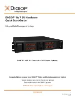
PowerEdge M600 System Board
Figure 7-12. PowerEdge M600 System Board Connectors
Table 7-17. PowerEdge M600 System Board Connectors
Connector
Description
1
-
Mezzanine card connector - Fabric C
2
-
Mezzanine card connector - Fabric B
3 BATTERY
Connector for the 3.0-V coin battery
4 1
Memory module connector, slot 1
5 5
Memory module connector, slot 5
6 2
Memory module connector, slot 2
7 6
Memory module connector, slot 6
8 3
Memory module connector, slot 3
9 7
Memory module connector, slot 7
10 4
Memory module connector, slot 4
11 8
Memory module connector, slot 8
12 CPU1
Processor 1 socket
2
1
4
5 6 7
8
9 10 11
12
13
14
15
16
17
18
3
Summary of Contents for PowerEdge M1000e
Page 1: ...Dell PowerEdge Modular Systems Hardware Owner s Manual ...
Page 56: ...56 About Your System Figure 1 21 Example of M610x Blade Port Mapping of Blade 2 ...
Page 64: ...64 About Your System Figure 1 23 Example of Half Height Blade Port Mapping ...
Page 126: ...126 About Your System ...
Page 144: ...144 Using the System Setup Program and UEFI Boot Manager ...
Page 264: ...264 Installing Blade Components ...
Page 286: ...286 Installing Enclosure Components ...
Page 308: ...308 Running System Diagnostics ...
Page 336: ...336 System Board Information ...
Page 338: ...338 Getting Help ...
Page 344: ...Index 344 V video controller installing 252 ...
Page 345: ...Index 345 ...
Page 346: ...346 Index ...