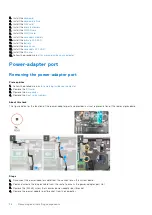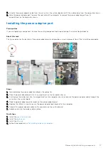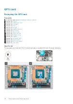
Steps
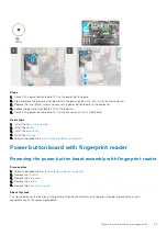
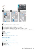
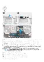
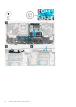
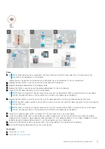
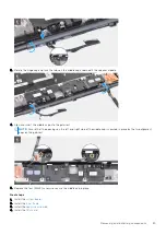
1. Carefully pry the outside end of the GPU power cable connector head to unlock the GPU power cable connector from the
system board on top side of the system.
2. Slightly slide the GPU power cable connector outwards to disconnect the GPU power cable from the connector on the
system board.
3. Disconnect the speaker cable and the SD card reader FPC from the connectors on the system board.
4. Disconnect the touch screen cable (for models shipped with a touch screen) or IR camera cable (for models shipped with an
IR camera), power adapter cable, touchpad FFC, USH daughter board FFC (for models shipped with a USH daughter board),
and power button board FFC from the system board.
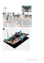
5. Remove the four (M2x3) screws that secure the two FPC beam connectors to the system board and the GPU card.
NOTE:
For computers shipped with a UMA GPU card
, remove the two (M2x3) screws that secure the single FPC
beam connector to the system board and the GPU card.
6. Remove the FPC beam connectors from the computer.
7. Remove the (M2x5) screw that secures the display cable bracket in place.
8. Remove the display cable bracket from the computer.
9. Disconnect the display cable from the connector on the system board.
10. Remove the four (M2x5) screws that secure the system board to the computer.
72
Removing and installing components
Summary of Contents for OptiPlex 7760
Page 1: ...Precision 7760 Service Manual Regulatory Model P44E Regulatory Type P44E002 July 2021 Rev A01 ...
Page 17: ...For computers without SSD door configuration Removing and installing components 17 ...
Page 25: ...Removing and installing components 25 ...
Page 29: ...Removing and installing components 29 ...
Page 74: ...74 Removing and installing components ...
Page 87: ...Removing and installing components 87 ...
Page 97: ...Removing and installing components 97 ...
Page 98: ...98 Removing and installing components ...

