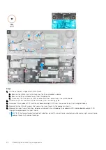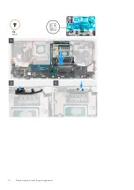
Steps
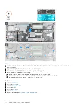
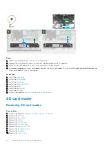
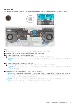
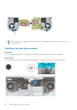
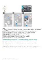
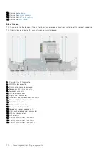
1. Align and insert the heat-sink assembly into its slot on the computer.
2. For the computers shipped with UMA graphics card:
a. Tighten the four captive screws to secure the heat-sink assembly to the system board.
NOTE:
Tighten the captive screws in the order stamped onto the heat sink next to the screws [1 > 2 > 3 > 4].
3. For the computers shipped with discrete graphics card:
a. Tighten the eight captive screws to secure the heat-sink assembly to the system board.
NOTE:
Tighten the captive screws in the order stamped onto the heat sink next to the screws [1 > 2 > 3 > 4 > 5 > 6
> 7 > 8].
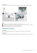
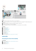
4. Connect the two fan cables to the connector on the system board.
5. Adhere the power-adapter cable on the heat-sink assembly.
6. Connect the power-adapter cable to the connector on the system board.
Next steps
1. Install the
.
2. Install the
.
3. Install the
.
after working inside your computer
.
Power button board
Removing the power button board
Prerequisites
before working inside your computer
.
2. Remove the
.
3. Remove the
.
4. Remove the
.
5. Remove the
.
About this task
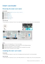
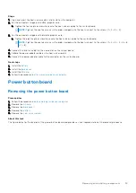
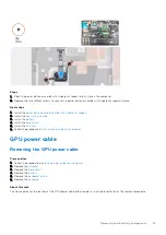
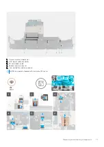
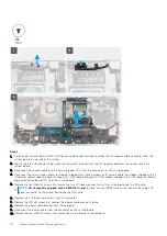
The figure indicates the location of the power button board and provides a visual representation of the removal procedure.
Removing and installing components
59
Summary of Contents for OptiPlex 7760
Page 1: ...Precision 7760 Service Manual Regulatory Model P44E Regulatory Type P44E002 July 2021 Rev A01 ...
Page 17: ...For computers without SSD door configuration Removing and installing components 17 ...
Page 25: ...Removing and installing components 25 ...
Page 29: ...Removing and installing components 29 ...
Page 74: ...74 Removing and installing components ...
Page 87: ...Removing and installing components 87 ...
Page 97: ...Removing and installing components 97 ...
Page 98: ...98 Removing and installing components ...

