background image

Steps

1. Ensure that you follow the 

Safety Instruction

.

2. Ensure that your work surface is flat and clean to prevent the computer cover from being scratched.
3. Turn off your computer.
4. Disconnect all network cables from the computer.

CAUTION:

 To disconnect a network cable, first unplug the cable from your computer and then unplug the

cable from the network device.

5. Disconnect your computer and all attached devices from their electrical outlets.
6. Press and hold the power button while the computer is unplugged to ground the system board.

NOTE:

 To avoid electrostatic discharge, ground yourself by using a wrist grounding strap or by periodically touching an

unpainted metal surface at the same time as touching a connector on the back of the computer.

Turning off your computer

Turning off your — Windows

About this task

CAUTION:

 To avoid losing data, save and close all open files and exit all open programs before you turn off your

computer .

Steps

1. Click or tap 

.

2. Click or tap 

 and then click or tap 

Shut down

.

NOTE:

 Ensure that the computer and all attached devices are turned off. If your computer and attached devices did not

automatically turn off when you shut down your operating system, press and hold the power button for about 6 seconds
to turn them off.

Turning off your computer — Windows 7

About this task

CAUTION:

 To avoid losing data, save and close all open files and exit all open programs before you turn off your

computer.

Steps

1. Click 

Start

.

2. Click 

Shut Down

.

NOTE:

 Ensure that the computer and all attached devices are turned off. If your computer and attached devices did not

automatically turn off when you shut down your operating system, press and hold the power button for about 6 seconds
to turn them off.

Working on your computer

7

Summary of Contents for OptiPlex 7050 Micro

Page 1: ...OptiPlex 7050 Micro Owner s Manual Regulatory Model D10U Regulatory Type D10U002 June 2020 Rev A03 ...

Page 2: ...attery 12 Installing coin cell battery 13 Storage 13 Removing 2 5 inch drive assembly 13 Removing the 2 5 inch drive from the drive bracket 14 Installing the drive into the drive bracket 14 Installing 2 5 inch drive assembly 15 WLAN card 15 Removing the WLAN card 15 Installing the WLAN card 16 M 2 PCIe SSD 16 Removing the M 2 PCIe SSD 16 Installing the M 2 PCIe SSD 17 System fan 17 Removing system...

Page 3: ...OS in Windows 44 Updating the BIOS in Linux and Ubuntu 45 Updating the BIOS using the USB drive in Windows 45 Updating the BIOS from the F12 One Time boot menu 45 System and setup password 46 Assigning a system setup password 46 Deleting or changing an existing system setup password 47 Clearing CMOS settings 47 Clearing BIOS System Setup and System passwords 48 Chapter 6 Software 49 Supported oper...

Page 4: ...iFi power cycle 62 Chapter 8 Technical specifications 63 Processor specifications 63 Memory specifications 64 Video specifications 64 Audio specifications 64 Communication specifications 64 Storage specifications 64 Ports and connectors specifications 65 Power supply specifications 65 Physical dimension specifications 65 Controls and lights specifications 66 Environmental specifications 66 Chapter...

Page 5: ...ential damage to hardware or loss of data and tells you how to avoid the problem WARNING A WARNING indicates a potential for property damage personal injury or death 2017 Dell Inc or its subsidiaries All rights reserved Dell EMC and other trademarks are trademarks of Dell Inc or its subsidiaries Other trademarks may be trademarks of their respective owners ...

Page 6: ... as directed by the online or telephone service and support team Damage due to servicing that is not authorized by Dell is not covered by your warranty Read and follow the safety instructions that came with the product CAUTION To avoid electrostatic discharge ground yourself by using a wrist grounding strap or by periodically touching an unpainted metal surface at the same time as touching a conne...

Page 7: ...uter Turning off your Windows About this task CAUTION To avoid losing data save and close all open files and exit all open programs before you turn off your computer Steps 1 Click or tap 2 Click or tap and then click or tap Shut down NOTE Ensure that the computer and all attached devices are turned off If your computer and attached devices did not automatically turn off when you shut down your ope...

Page 8: ... Steps 1 Connect any telephone or network cables to your computer CAUTION To connect a network cable first plug the cable into the network device and then plug it into the computer 2 Connect your computer and all attached devices to their electrical outlets 3 Turn on your computer 4 If required verify that the computer works correctly by running ePSA diagnostics 8 Working on your computer ...

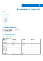
Page 9: ...Phillips 1 screwdriver Small plastic scribe Screw information This topic lists the screw information Table 1 Screw size list Component Secured to Screw type Quantity Top cover Chassis Bottom cover 6 32 9 3 1 System Board Chassis 6 32 5 4 3 HDD support bracket Chassis 6 32 5 4 1 SDD card and WiFi card Stand off Chassis M3X4 2 Thermal Module Heatsink 35W Chassis M3 4 Thermal Module Heatsink 65W Chas...

Page 10: ...i card Stand off M2X3 5 1 Solid state drive Stand off M2X3 5 1 Antenna Removing antenna Steps 1 Follow the procedure in Before working inside your computer 2 Loosen the antenna screw to remove the antenna from the computer Installing antenna Steps 1 Align the antenna and tighten the screw secure the antenna to the computer 10 Disassembly and reassembly ...

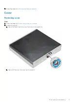
Page 11: ... Cover Removing cover Steps 1 Follow the procedure in Before working inside your computer 2 To remove the cover a Loosen the thumbscrew that secures the cover to the computer 1 b Slide and lift the cover to remove from the computer Disassembly and reassembly 11 ...

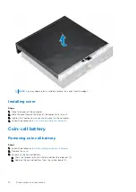
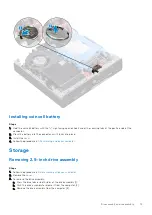
Page 12: ...ew to secure the cover to the computer 4 Follow the procedure in After working inside your computer Coin cell battery Removing coin cell battery Steps 1 Follow the procedure in Before working inside your computer 2 Remove the cover 3 To remove the coin cell battery a Press the release latch until the coin cell battery pops out 1 b Remove the coin cell battery from the system board 2 12 Disassembly...

Page 13: ...stall the cover 4 Follow the procedure in After working inside your computer Storage Removing 2 5 inch drive assembly Steps 1 Follow the procedure in Before working inside your computer 2 Remove the cover 3 To remove the drive assembly a Press the blue tabs on both sides of the drive assembly 1 b Push the drive assembly to release it from the computer 2 c Remove the drive assembly from the compute...

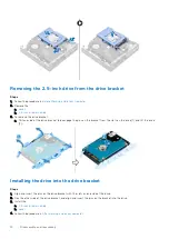
Page 14: ...pins on the bracket from the slots on the drive 1 and lift the drive 2 Installing the drive into the drive bracket Steps 1 Align and insert the pins on the drive bracket with the slots on one side of the drive 2 Flex the other side of the drive bracket and align and insert the pins on the bracket into the drive 3 Install the a 2 5 inch drive assembly b cover 4 Follow the procedure in After working...

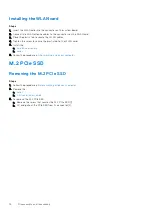
Page 15: ...ur computer WLAN card Removing the WLAN card Steps 1 Follow the procedure in Before working inside your computer 2 Remove the a cover b hard drive assembly 3 To remove the WLAN card a Remove the screw that secures the plastic tab 1 b Remove the plastic tab to access the WLAN cables 2 c Disconnect the WLAN cables from the connectors on the WLAN card 3 d Lift the WLAN card from the connector on the ...

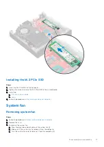
Page 16: ...astic tab to the WLAN card 5 Install the a hard drive assembly b cover 6 Follow the procedure in After working inside your computer M 2 PCIe SSD Removing the M 2 PCIe SSD Steps 1 Follow the procedure in Before working inside your computer 2 Remove the a cover b 2 5 inch drive assembly 3 To remove the M 2 PCIe SSD a Remove the screw that secures the M 2 PCIe SSD 1 b Lift and pull out the PCIe SSD f...

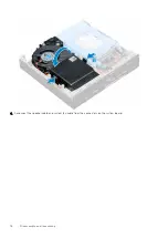
Page 17: ...e procedure in After working inside your computer System fan Removing system fan Steps 1 Follow the procedure in Before working inside your computer 2 Remove the cover 3 To remove the system fan a Press the blue tabs on both sides of the system fan 1 b Slide and lift the system fan to release it from the computer c Turn the system fan over to remove it from the computer 2 Disassembly and reassembl...

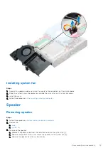
Page 18: ...4 Disconnect the speaker cable and system fan cable from the connectors on the system board 18 Disassembly and reassembly ...

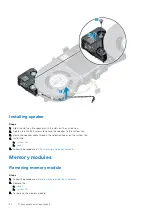
Page 19: ...4 Follow the procedure in After working inside your computer Speaker Removing speaker Steps 1 Follow the procedure in Before working inside your computer 2 Remove the a cover b system fan 3 To remove the speaker a Release the speaker cable from the retention hooks on the system fan 1 b Remove the M2 5X4 screws that secure the speaker to the system fan 2 c Remove the speaker from the system fan 3 D...

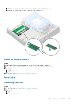
Page 20: ...oute the speaker cable through the retention hooks on the system fan 4 Install the a system fan b cover 5 Follow the procedure in After working inside your computer Memory modules Removing memory module Steps 1 Follow the procedure in Before working inside your computer 2 Remove the a cover b system fan 3 To remove the memory module 20 Disassembly and reassembly ...

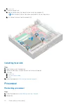
Page 21: ...dule with the tab on the memory module connector 2 Insert the memory module into the memory module socket and press it until it clicks into place 3 Install the a system fan b cover 4 Follow the procedure in After working inside your computer Heat sink Removing heat sink Steps 1 Follow the procedure in Before working inside your computer 2 Remove the a cover b 2 5 inch drive assembly Disassembly an...

Page 22: ...e computer 2 Installing heat sink Steps 1 Place the heat sink on the processor 2 Tighten the M3 screws to secure the heat sink to the system board 3 Install the a system fan b 2 5 inch drive assembly c cover 4 Follow the procedure in After working inside your computer Processor Removing processor Steps 1 Follow the procedure in Before Working Inside Your Computer 2 Remove the 22 Disassembly and re...

Page 23: ... of the socket 3 NOTE After removing the processor place it in an antistatic container for reuse return or temporary storage Do not touch the bottom of the processor to avoid damage to the processor contacts Touch only the side edges of the processor Installing processor Steps 1 Align the processor with the socket keys CAUTION Do not use force to seat the processor When the processor is positioned...

Page 24: ...e procedure in After working inside your computer System board Removing system board Steps 1 Follow the procedure in Before working inside your computer 2 Remove the a cover b 2 5 inch drive assembly c system fan d heat sink e processor 3 To remove the plastic tab a Remove the screw that secures the plastic tab to the system board 1 b Lift the plastic tab away from the system board 2 24 Disassembl...

Page 25: ...move the 6 32 5 4 screws that secure the system board to the computer 1 b Slide the system board to disengage the connectors from the back of the computer 2 c Lift the system board away from the computer 3 Disassembly and reassembly 25 ...

Page 26: ...sis and the screw holes on the system board align with the standoffs on the computer 3 Tighten the 6 32 5 4 screws to secure the system board to the computer 4 Place the metal tab on the system board and tighten the screw to secure the metal tab to the system board 5 Install the a processor b heat sink c system fan d 2 5 inch drive assembly e cover 6 Follow the procedure in After working inside yo...

Page 27: ...Memory module connectors 5 M 2 WLAN connector 6 Power switch connector 7 Hard drive connector 8 M 2 SSD connector 9 Coin cell battery 10 Service Mode Jumper 11 Clear password jumper 12 Clear CMOS jumper 13 DP VGA connector optional 14 PS 2 serial connector optional Disassembly and reassembly 27 ...

Page 28: ...the latest Intel Rapid Storage Technology Intel RST 15 5X The Intel OptaneTM memory module includes these key features PCIe 3 0x2 with NVMe interface Uses Intel s revolutionary new storage technology 3D XpointTM memory media Ultra low latency exceptional responsiveness Performance saturation at queue depth of 4 and lower Very high endurance capabilities Intel OptaneTM Memory Module Driver Requirem...

Page 29: ...he white adhesive tape c Place the M 2 Intel optane memory module into the slot on the thermal pad d If the system is shipped with screw tighten that secures the M 2 Intel optane memory module on the computer If the system is shipped with self locking spacer press to lock the M 2 Intel optane to secure on the computer M 2 Intel Optane Memory Module 16 GB 29 ...

Page 30: ...echnology 15 2 or later Operating System Support Windows 10 64 bit Supported Platforms 7th generation or newer Intel Core processor based platforms Power 3 3V Supply Rail Active 3 5 W Drive Idel 900mW to 1 2W Compliance NVMe Express 1 1 PCI Express Base specifiation rev 3 0 PCI M 2 HS Spec Certification and Declarationsµ UL CE C Tick BSMI KCC Microsoft WHQL Microsoft WHCK VCCI Endurance Rating 100...

Page 31: ...mperature is targeted for 70º C 2 Please contact your Intel representative for details on the non operating temperature range 3 Temperature gradient measured without condensation 4 Shock specification assume the device is mounted securely with the input vibration applied to the drive mounting screws Stimulus may be applied in the X Y or Z axis and shock specification is measured using Root Mean Sq...

Page 32: ...EL MEMPEK1W016GA 2 During the first time boot up the system will scan the pairing status as below screen shot after shutdown It s working as designed and the message will not appear again in following boot ups 32 M 2 Intel Optane Memory Module 16 GB ...

Page 33: ... than its predecessor In a nutshell USB 3 1 Gen 1 features are as follows Higher transfer rates up to 5 Gbps Increased maximum bus power and increased device current draw to better accommodate power hungry devices New power management features Full duplex data transfers and support for new transfer types Backward USB 2 0 compatibility New connectors and cable The topics below cover some of the mos...

Page 34: ...at much better Single link DVI requires almost 2Gbps throughput Where 480Mbps was limiting 5Gbps is more than promising With its promised 4 8Gbps speed the standard will find its way into some products that previously weren t USB territory like external RAID storage systems Listed below are some of the available SuperSpeed USB 3 0 USB 3 1 Gen 1 products External Desktop USB 3 0 USB 3 1 Gen 1 Hard ...

Page 35: ...am to a surround audio system eliminating the need for a separate audio cable 3D Defines input output protocols for major 3D video formats paving the way for true 3D gaming and 3D home theater applications Content Type Real time signaling of content types between display and source devices enabling a TV to optimize picture settings based on content type Additional Color Spaces Adds support for add...

Page 36: ...s the user password type of hard drive installed and enabling or disabling base devices Topics BIOS overview Entering BIOS setup program Navigation keys One time boot menu System Setup options Updating the BIOS System and setup password Clearing CMOS settings Clearing BIOS System Setup and System passwords BIOS overview The BIOS manages data flow between the computer s operating system and attache...

Page 37: ...ilable STXXXX Drive if available NOTE XXX denotes the SATA drive number Optical Drive if available SATA Hard Drive if available Diagnostics The boot sequence screen also displays the option to access the System Setup screen System Setup options NOTE Depending on the computer and its installed devices the items listed in this section may or may not appear Table 7 General Option Description System I...

Page 38: ...efault The options are Disabled Enabled Enabled w PXE default NOTE Depending on the computer and its installed devices the items listed in this section may or may not appear SATA Operation Allows you to configure the operating mode of the integrated hard drive controller Disabled The SATA controllers are hidden RAID ON SATA is configured to support RAID mode selected by default AHCI SATA is config...

Page 39: ...n Primary Display Allows you to select the primary display when multiple controllers are available in the system Auto default Intel HD Graphics NOTE If you do not select Auto the on board graphics device will be present and enabled Table 10 Security Option Description Admin Password Allows you to set change and delete the admin password System Password Allows you to set change and delete the syste...

Page 40: ...llows you to control whether the Trusted Platform Module TPM is visible to the operating system TPM On default Clear PPI Bypass for Enable Commands PPI Bypass for Disable Commands Attestation Enable default Key Storage Enable default SHA 256 default Disabled Enabled default Computrace This field lets you Activate or Disable the BIOS module interface of the optional Computrace Service from Absolute...

Page 41: ...able the Custom Mode the relevant options for PK KEK db and dbx appear The options are Save to File Saves the key to a user selected file Replace from File Replaces the current key with a key from a user selected file Append from File Adds a key to the current database from a user selected file Delete Deletes the selected key Reset All Keys Resets to default setting Delete All Keys Deletes all the...

Page 42: ...y turn on the computer Time is kept in standard 12 hour format hour minutes seconds Change the startup time by typing the values in the time and AM PM fields NOTE This feature does not work if you turn off your computer using the switch on a power strip or surge protector or if Auto Power is set to disabled Deep Sleep Control Allows you to define the controls when Deep Sleep is enabled Disabled En...

Page 43: ...s option is disabled by default Fast Boot This option can speed up the boot process by bypassing some compatibility steps Minimal The system boots quickly unless the BIOS has been updated memory changed or the previous POST did not complete Thorough The system does not skip any steps in the boot process Auto This allows the operating system to control this setting this works only when the operatin...

Page 44: ...default Table 19 System Logs Option Description BIOS Events Displays the system event log and allows you to Clear Log Mark all Entries Table 20 Advanced configurations Option Description ASPM Allows you to activate the state power management Auto Default Disabled L1 Only Updating the BIOS Updating the BIOS in Windows About this task CAUTION If BitLocker is not suspended before updating the BIOS th...

Page 45: ...formation see the knowledge base article 000145519 at www dell com support 3 Copy the BIOS setup program file to the bootable USB drive 4 Connect the bootable USB drive to the computer that needs the BIOS update 5 Restart the computer and press F12 6 Select the USB drive from the One Time Boot Menu 7 Type the BIOS setup program filename and press Enter The BIOS Update Utility appears 8 Follow the ...

Page 46: ...ick Flash from file 4 Select external USB device 5 Select the file and double click the flash target file and then click Submit 6 Click Update BIOS The computer restarts to flash the BIOS 7 The computer will restart after the BIOS update is completed System and setup password Table 21 System and setup password Password type Description System password Password that you must enter to log in to your...

Page 47: ...y after a power on or reboot Steps 1 In the System BIOS or System Setup screen select System Security and press Enter The System Security screen is displayed 2 In the System Security screen verify that Password Status is Unlocked 3 Select System Password update or delete the existing system password and press Enter or Tab 4 Select Setup Password update or delete the existing setup password and pre...

Page 48: ...k To clear the system or BIOS passwords contact Dell technical support as described at www dell com contactdell NOTE For information on how to reset Windows or application passwords refer to the documentation accompanying Windows or your application 48 BIOS setup ...

Page 49: ...n V6 0 OS Media Support Optional USB optical drive Downloading drivers Steps 1 Turn on the computer 2 Go to Dell com support 3 Click Product Support enter the Service Tag of your computer and then click Submit NOTE If you do not have the Service Tag use the auto detect feature or manually browse for your computer model 4 Click Drivers and Downloads 5 Select the operating system installed on your c...

Page 50: ...puter 8 After the download is complete navigate to the folder where you saved the driver file 9 Double click the chipset driver file icon and follow the instructions on the screen Intel chipset drivers Verify if the Intel chipset drivers are already installed in the computer NOTE Click Start Control Panel Device Manager or In Search the web and Windows type Device Manager Table 23 Intel chipset dr...

Page 51: ...Table 24 Intel HD Graphics drivers Before installation After installation Software 51 ...

Page 52: ...performs a complete check of your hardware The Dell SupportAssist Pre boot System Performance Check diagnostics is embedded with the BIOS and is launched by the BIOS internally The embedded system diagnostics provides a set of options for particular devices or device groups allowing you to Run tests automatically or in an interactive mode Repeat tests Display or save test results Run thorough test...

Page 53: ...s and power extension cables to verify that the computer turns on properly Ensure the electrical outlet is working by testing it with another device such as a lamp Solid amber blinking amber The second state of the LED at power up indicates that the POWER_GOOD signal is active and it is probable that the power supply is fine Initial State of LED at power up Refer to the table below for Blinking Am...

Page 54: ...sist to troubleshoot narrow down the issue with PSU BIST Test reseat cable If nothing works replace the motherboard power supply or cabling 2 blinks short pause 3 blinks long pause repeats Bad Motherboard Memory or Processor If customer can assist to troubleshoot narrow down the issue by reseating memory and swapping an available known good memory If nothing works replace the motherboard memory or...

Page 55: ...ailures PCIe device configuration activity is in progress or PCIe device failure was detected If customer can assist to troubleshoot narrow down the issue by reseating PCIe card and removing one by one to determine which card failed If identified the PCIe card failed replace the PCIe Card If none of the PCIe Cards failed replace the motherboard S5 VID 3 blinks short pause 2 blinks long pause repea...

Page 56: ...n assist to troubleshoot narrow down the issue by removing one by one storages on motherboard to determine which one failed If identified the storage failed replace the storage If identified the storage failed replace the storage S8 MEM 3 blinks short pause 5 blinks long pause repeats Memory configuration or incompatible error Memory subsystem configuration activity is in progress No memory module...

Page 57: ...ine which one failed If identified the memory failed replace the memory If else replace the motherboard WARNING The power LED only serve as an indicator of the progress through the POST process These LEDs do not indicate the problem that caused the POST routine to stop Power LED issue Power LED is not flashing amber on ChengMing 3977 and Optiplex D8 and OptiPlex D8 AIO platforms ChengMing 3977 and...

Page 58: ...er card EXTENDED MEMORY SIZE HAS CHANGED The amount of memory recorded in non volatile memory NVRAM does not match the memory module installed in the computer Restart the computer If the error appears again Contact Dell THE FILE BEING COPIED IS TOO LARGE FOR THE DESTINATION DRIVE The file that you are trying to copy is too large to fit on the disk or the disk is full Try copying the file to a diff...

Page 59: ...KEYBOARD DATA LINE FAILURE For external keyboards check the cable connection Run the Keyboard Controller test in Dell Diagnostics KEYBOARD STUCK KEY FAILURE For external keyboards or keypads check the cable connection Restart the computer and avoid touching the keyboard or keys during the boot routine Run the Stuck Key test in Dell Diagnostics LICENSED CONTENT IS NOT ACCESSIBLE IN MEDIADIRECT Dell...

Page 60: ...ics If the message reappears Contact Dell TIME OF DAY CLOCK LOST POWER System configuration settings are corrupted Connect your computer to an electrical outlet to charge the battery If the problem persists try to restore the data by entering the System Setup program then immediately exit the program If the message reappears Contact Dell TIME OF DAY CLOCK STOPPED The reserve battery that supports ...

Page 61: ...ed to complete the boot routine three consecutive times for the same error CMOS checksum error RTC is reset BIOS Setup default has been loaded CPU fan failure CPU fan has failed System fan failure System fan has failed Hard disk drive failure Possible hard disk drive failure during POST Keyboard failure Keyboard failure or loose cable If reseating the cable does not solve the problem replace the k...

Page 62: ...C reset function allows you or the service technician to recover Dell systems from No POST No Power No Boot situations The legacy jumper enabled RTC reset has been retired on these models Start the RTC reset with the system powered off and connected to AC power Press and hold the power button for 20 seconds The system RTC Reset occurs after you release the power button Backup media and recovery op...

Page 63: ...MB cache depending on processor type Feature Specification Processor type Intel Core i3 6100 DC 3MB 4T 3 7GHz 65W Intel Core i3 6100T DC 3MB 4T 3 2GHz 35W Intel Core i5 6400T QC 6MB 4T 2 2GHz 35W Intel Core i5 6500 QC 6MB 4T 3 2GHz 65W Intel Core i5 6500T QC 6MB 4T 2 5GHz 35W Intel Core i5 6600 QC 6MB 4T 3 3GHz 65W Intel Core i5 6600T QC 6MB 4T 2 7GHz 35W Intel Core i7 6700 QC 8MB 8T 3 4GHz 65W In...

Page 64: ...on Controller Realtek ALC3234 High Definition Audio Codec integrated supports multiple streaming Internal speaker amplifier Integrated Communication specifications Table 29 Communication specifications Feature Specification Network adapter Integrated Intel i219 V Gigabit1 Ethernet LAN 10 100 1000 Remote Wake Up PXE and support Wireless optional Intel Dual Band Wireless AC 8265 Wi Fi BT 4 2 Wireles...

Page 65: ...splayPort 1 2 one one optional HDMI port one Rear port PS 2 one optional Rear port RJ45 one Rear port PS 2 keyboard and mouse optional Power supply specifications Feature Specification Type 65 W 130 W Frequency 47 Hz 63 Hz Voltage 90 VAC 264 VAC Input current 1 7 A 1 0 A 1 8 A 0 9 A Coin cell battery 3 V CR2032 lithium coin cell Physical dimension specifications Feature Specification Width 35 56 m...

Page 66: ...rk adapter Yellow light A blinking yellow light indicates that network activity is present Power supply diagnostic light Green light The power supply is turned on and is functional The power cable must be connected to the power connector at the back of the computer and the electrical outlet Environmental specifications Temperature Specifications Operating 0 C to 35 C 32 F to 95 F Storage 40 C to 6...

Page 67: ...ick Search to retrieve the related articles Learn and know the following information about your product Product specifications Operating system Setting up and using your product Data backup Troubleshooting and diagnostics Factory and system restore BIOS information See Me and My Dell at www dell com support manuals To locate the Me and My Dell relevant to your product identify your product through...

Reviews: