background image

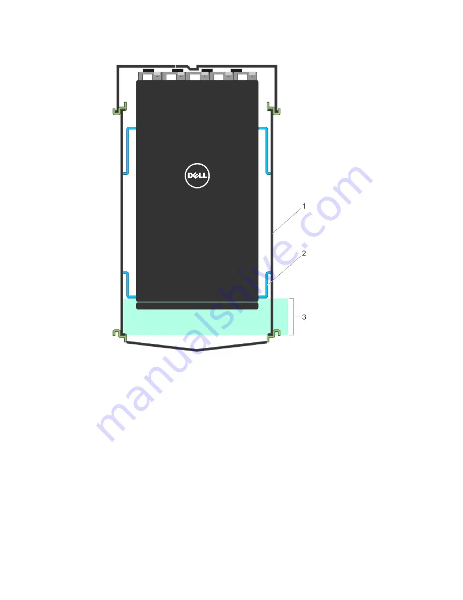
1.

Dell 4226 (1070 mm) cabinet outline

2.

Adjustable front vertical rail inside Dell 4226 

cabinet

3.

6.5 inches

1.

Align the system with rails and slide the system into rack.

2.

Tighten the screws on each side of the systems’s front panel (1).

3.

To remove the system from the rack, loosen the screws and slide the system out of the rack.

Z9500 Installation

25

Summary of Contents for Networking Z9500

Page 1: ...Dell Networking Installation Guide for the Z9500 Switch ...

Page 2: ...problem WARNING A WARNING indicates a potential for property damage personal injury or death Copyright 2014 Dell Inc All rights reserved This product is protected by U S and international copyright and intellectual property laws Dell and the Dell logo are trademarks of Dell Inc in the United States and or other jurisdictions All other marks and names mentioned herein may be trademarks of their res...

Page 3: ...Rails Mounting Brackets 20 Installing the Dell Static Rails System 20 Identifying the Rail Kit ContentsInstalling and Removing Tool less Rails Square Hole Installing and Removing Tooled Rails Threaded Hole Racks or Round Hole Racks 20 Mounting the Chassis in a Four Post Rack 23 Securing the Chassis Ground 27 Installing Fan Modules 28 Installing AC Power Supplies 29 Securing Power Cables 32 Install...

Page 4: ...nication Statement 41 European Union EMC Directive Conformance Statement 41 European Community Contact 42 Japan VCCI Compliance for Class A Equipment 42 Korean Certification of Compliance 43 Safety Standards and Compliance Agency Certifications 43 Electromagnetic Compatibility EMC 43 Product Recycling and Disposal 44 9 Technical Support 45 The iSupport Website 45 Accessing iSupport Services 45 Req...

Page 5: ...re you install and power up this equipment This equipment contains two power cords Disconnect both power cords before servicing WARNING This equipment contains optical transceivers which comply with the limits of Class 1 laser radiation WARNING When no cable is connected visible and invisible laser radiation may be emitted from the aperture of the optical transceiver ports Avoid exposure to laser ...

Page 6: ...6 ...

Page 7: ...nical Support Product Description The Z9500 is part of Dell Networking s Z Series family of Data Center Core switches The Z9500 switch is a compact 3 RU Rack Unit high performance and low latency 10 40 Gigabit Ethernet switch It runs the Dell Networking Operating Software OS providing features and capabilities that are widely deployed The Z9500 switch has the following features 132 fixed Quad Smal...

Page 8: ...8 ...

Page 9: ...ers Use an equipment lift or pallet jack to lift or install the chassis Lifting the system by its shelves will cause damage to the chassis Z9500 switch Static Rail kit 1 and 2 Phillips and flat tipped screwdrivers required NOTE One Rail Kit is required for every chassis in a rack Screws for rack installation Console cables Any optional items ordered Getting Started Guide Safety and Regulatory Info...

Page 10: ...6 Installing Fan Modules 7 Securing Power Cables 8 Installing the QSFP Optics 9 Installing the Cable Management System 10 Supplying Power and Powering Up the System 10 Unpacking the Switch ...

Page 11: ... provides one DB9 RS 232 console port with YOST RJ 45 pinout and a dedicated Ethernet service port for out of band OOB management functions I O Panel All fixed data ports 132 40GbE quad small form factor pluggable plus QSFP ports are on the I O panel Figure 1 I O Panel The I O panel includes 132 fixed Quad Small Form Factor Pluggable QSFP ports Light Emitting Diodes LEDs Management ports NOTE The ...

Page 12: ...upting traffic Fans The Z9500 supports five fan trays with airflow directions from I O to Utility The fans must be installed at the customer site System Status You can view Z9500 status information in several ways including LEDs CLI show commands Simple network management protocol SNMP For more information about these options refer to the Dell Networking Command Line Reference Guide and Dell Netwo...

Page 13: ... O Panel Label LED Color Display Description Alarm LED Off Amber solid Red solid No alarm Minor alarm Major alarm System status LED Off Green solid Green blinking No power Normal operation System is booting System locator LED Off Blue solid No activity Port locator Management port activity LED Off Green blinking No activity The port and the link are active and there is link activity Management por...

Page 14: ...ed interface fortyGigE tengigabitethernet SLOT PORT on command to locate the 10GbE 40GbE port and then press the channel selector button to locate the corresponding 10GbE port as shown in Figure 3 When port locator functionality is enabled on a port the corresponding port LED turns solid blue Table 2 40GbE Port LEDs Label LED Color Display Description Port locator LED Off Blue No activity Port loc...

Page 15: ... System LED Displays Utility Panel Label LED Color Display Description PSU status LED Green solid Amber Solid Off Normal operation Minor Major alarms Power not present Fan status LED Green solid Amber Solid Off Normal operation Minor Major alarms Power not present Hardware Overview 15 ...

Page 16: ...16 ...

Page 17: ...lowing safety requirements Near an adequate power source Connect the system to the appropriate branch circuit protection as defined by your local electrical codes Environmental temperature between 32 to 104 F 0 to 40 C Humidity that does not exceed 85 percent noncondensing In a dry clean well ventilated and temperature controlled room away from heat sources such as hot air vents or direct sunlight...

Page 18: ... are mishandled Always wear an ESD preventive wrist or heel ground strap when handling the Z9500 and its accessories After you remove the original packaging place the Z9500 and its components on an anti static surface 1 Storage temperature must remain constant ranging from 4 to 158 F 20 C to 70 C 2 Store on a dry surface or floor away from direct sunlight heat and air conditioning ducts 3 Store in...

Page 19: ... Ground 5 Installing Fan Modules 6 Installing AC Power Supplies 7 Securing Power Cables 8 Installing the Cable Management System 9 Installing the QSFP Optics 10 Supplying Power and Powering Up the System Assemble 4 Post Rack Frame The chassis can be installed only in a 4 post rack frame Follow the instructions in your rack frame kit to install the 4 post rack frame Z9500 Installation 19 ...

Page 20: ... of the chassis using eight screws for each bracket Attach the bracket so that the ear faces to the I O side and the outside of the chassis 1 Utility side of the chassis 2 Screws 3 Static rail mounting bracket Installing the Dell Static Rails System Dell Networking provides the Static Rails rack mounting system so you can easily configure a rack to install the switch Identifying the Rail Kit Conte...

Page 21: ...piece in the bottom and top holes of the desired U spaces 2 3 Engage the back end of the rail until it fully seats on the vertical rack flange and the latch clicks into place Repeat these steps to position and seat the front end piece on the vertical flange NOTE Make sure the blue release latch is closed 4 To remove the rails pull on the blue release latch on each end piece and unseat the rail fro...

Page 22: ...d screwdriver 2 2 Pull on the rail latch subassemblies to remove them from the mounting brackets 1 3 Attach the left and right mounting rails to the front vertical rack flanges using two pairs of screws 4 Slide the left and right rear brackets forward against the rear vertical rack flanges and attach them using two pairs of screws 3 22 Z9500 Installation ...

Page 23: ...sult in shelf or rack failure which may damage equipment and cause possible personal injury Stabilize racks in a permanent location before loading begins Mount the components beginning at the bottom of the rack then work to the top Do not exceed your rack load rating Power considerations Connect only to the power source specified on the unit When multiple electrical components are installed in a r...

Page 24: ...ure cool air intake and to avoid hot air blow out from I O panel Reliable earthing Maintain reliable earthing of rack mounted equipment Pay particular attention to the supply connections other than the direct connections to the branch circuit for example use of power strips Do not mount the equipment with the Utility panel facing in the downward position NOTE The illustrations in this document are...

Page 25: ...ide Dell 4226 cabinet 3 6 5 inches 1 Align the system with rails and slide the system into rack 2 Tighten the screws on each side of the systems s front panel 1 3 To remove the system from the rack loosen the screws and slide the system out of the rack Z9500 Installation 25 ...

Page 26: ...1 Additional screw to restrict front back movement of the switch 2 Main screw 26 Z9500 Installation ...

Page 27: ...r is green or green with yellow stripe NOTE For proper ventilation position the chassis in an equipment rack or cabinet with a minimum of 5 inches 12 7 cm of clearance around exhaust vents The acceptable ambient temperature ranges are listed in the Environmental Parameters section Use M5 screws 3 Tighten the screws torque should be between 18 and 24 inch lbs 4 Connect the opposite end of the groun...

Page 28: ... higher average fan life The switch increases the fan speed to maximum if the facility air condition fails or if a fan fails The fan speed increases and decreases automatically based on the internal temperature The switch never intentionally turns off the fans For proper ventilation position the switch in an equipment rack or cabinet with a minimum of 5 inches 12 7 cm of clearance around the exhau...

Page 29: ... slot smoothly Do not force a PSU into a slot as this action may damage the PSU or the chassis The chassis supports AC power supplies with air flow direction from I O to Utility For PSUs a LED indicates the power status To view the log messages use the show logging command For more information refer to the System Logs chapters of the Dell Networking OS Command Line Reference Guide for the Z9500 Sw...

Page 30: ...b handle to slide the PSU into the switch PSU slot The PSU slot is keyed so that the PSU can be fully inserted in only one way When you install the PSU correctly it snaps into place and is flush with the back of the switch Figure 8 Installing an AC Power Supply 1 Release latch 2 Slot 0 for AC PSU 0 CAUTION Fan tray modules must be inserted before powering up the switch CAUTION The switch has a hig...

Page 31: ...CAUTION Always disconnect the power cable before you service the power supply slots CAUTION Use the power supply cord as the main disconnect device on the AC system Ensure that the socket outlet is located installed near the equipment and is easily accessible 4 Repeat steps 1 through 3 above for all PSUs NOTE Ensure that the PSU is correctly installed When you correctly install the PSU the power c...

Page 32: ... power supply Installing the Cable Management System OPTIONAL You must order the cable management mount assembly separately Mount the assembly on the top front of the chassis to organize network cables and to minimize obstruction from these cables while you insert remove and view the chassis components Using the cable management system you can attach the maximum number of cables in Z9500 I O ports...

Page 33: ...ble Management System for DAC Cables 1 Pin rack unit for DAC cable routing 2 Rack unit for DAC cable routing 2 Insert a cable in a Z9500 port then route the DAC cables up and along the line card face between the larger pins directly above the card Position the cables so they follow the channel marked in the figure below and exit to the right or left depending on the chassis slot location The cable...

Page 34: ...able Management System 1 Pin rack unit for DAC cable routing 2 Rack unit for DAC cable routing NOTE To fully populate the cable management system in a 1070 mm cabinet the maximum supported length of the DAC cable is 5 m 34 Z9500 Installation ...

Page 35: ...20 36 40 44 60 64 68 84 88 92 108 112 116 132 136 and 140 Line card 1 only in ports 12 16 20 36 40 44 60 64 68 84 88 92 108 112 116 132 136 140 156 160 164 180 184 and 188 Line card 2 only in ports 12 16 20 36 40 44 60 64 68 84 88 92 108 112 116 132 136 140 156 160 164 180 184 and 188 When the switch operates in a reduced ambient temperature you can use LR4 optics in any port See Port Numbering Co...

Page 36: ...ts are numbered from bottom to top in multiples of four starting with zero for example 0 4 8 12 and so on When a breakout cable is installed the resulting four 10GbE ports are numbered with the remaining numbers For example 40GbE port 0 contains 10GbE ports 0 1 2 and 3 40GbE port 4 contains 10GbE ports 4 5 6 and 7 Line card 0 consists of ports 0 to 143 line card 1 consists of ports 0 to 191 line c...

Page 37: ...e ambient temperature around the unit which may be higher than the room temperature is within the limits specified for the switch There is sufficient airflow around the chassis The input circuits are correctly sized for the loads and that you use sufficient overcurrent protection devices NOTE For powering up the AC PSUs AC power cables are included in the shipping container You must order all othe...

Page 38: ...38 ...

Page 39: ...tal Parameters Parameter Specifications Operating temperature 32 to 104 F 0 to 40 C Operating humidity 10 to 85 percent RH noncondensing Storage temperature 40 to 158 F 40 to 70 C Storage humidity 5 to 95 percent RH noncondensing Maximum thermal output 10567 BTU hr Maximum Altitude No performance degradation up to 6600ft Ambience derating required for higher altitude Table 6 Power Requirements Par...

Page 40: ...40 ...

Page 41: ...ommended cables and connectors or by unauthorized changes or modifications in the equipment Unauthorized changes or modification could void the user s authority to operate the equipment This device complies with Part 15 of the FCC Rules Operation is subject to the following two conditions This device may not cause harmful interference This device must accept any interference received including int...

Page 42: ...nweg 19 66265 Heusweiler Germany http www force10networks com german Japan VCCI Compliance for Class A Equipment WARNING Use the AC power cords with Dell Networking equipment only Do not use Dell Networking AC power cords with any unauthorized hardware This is Class A product based on the standard of the Voluntary Control Council For Interference by Information Technology Equipment VCCI If this eq...

Page 43: ... Regulation 21CFR 1040 10 and 1040 11 IEC 60950 1 Second Edition including all National Deviations and Group Differences Electromagnetic Compatibility EMC Emissions International CISPR 22 2006 Class A Australia New Zealand AS NZS CISPR 22 2009 Class A Canada ICES 003 Issue 4 Class A Europe EN55022 2006 CISPR 22 2006 Class A Japan VCCI V 3 2011 04 Class A USA FCC CFR47 Part 15 Subpart B Class A Imm...

Page 44: ... that the product is not to be thrown away but rather reclaimed upon end of life per this Directive Figure 15 The European WEEE symbol In accordance with the European WEEE Directive electrical and electronic equipment EEE is to be collected separately and to be reused recycled or recovered at end of life Users of EEE with the WEEE marking per Annex IV of the WEEE Directive as shown above must not ...

Page 45: ...rking products access to software upgrades and patches and open and manage your Tech Support cases Dell Networking iSupport provides integrated secure access to these services Accessing iSupport Services The URL for iSupport is http www force10networks com CSPortal20 Main Login aspx You must have a userid and password to access iSupport services 1 On the Dell Networking Support page click the Acco...

Page 46: ... Output from the show logging command on the unit that experienced the failure This report is included as a section in the output of show tech support command Console captures showing the error messages Console captures showing the troubleshooting steps taken Saved messages to a syslog server if you use one Contacting Technical Support How to Contact Dell Networking Tech Support Log in to iSupport...

Page 47: ...ftware Updates Log in to iSupport and select the Software Center tab Technical Documentation Log in to iSupport and select the Documents tab You can access this page without logging in using the Documentation link on the iSupport page Contact Information E mail Dell Force10_Technical_Support Dell com Web http support dell com Telephone USA 1 866 965 5800 International 408 965 5800 Technical Suppor...

Reviews: