background image

9.

Lift and remove the smart card reader from the computer.

Installing the Smart Card Reader

1.

Place the smart card reader in the compartment.

2.

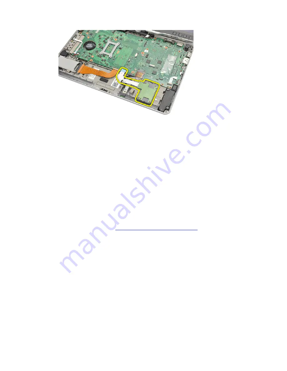
Connect the smart card reader flex cable to the system board.

3.

Replace the palmrest.

4.

Replace the back cover.

5.

Replace the hard drive assembly.

6.

Replace the keyboard.

7.

Replace the keyboard trim.

8.

Replace the back panel.

9.

Replace the battery.

10. Follow the procedures in 

After Working Inside Your Computer.

78

Summary of Contents for Latitude XT3

Page 1: ...Dell Latitude XT3 Owner s Manual Regulatory Model P17G Regulatory Type P17G001 ...

Page 2: ...problem WARNING A WARNING indicates a potential for property damage personal injury or death Copyright 2014 Dell Inc All rights reserved This product is protected by U S and international copyright and intellectual property laws Dell and the Dell logo are trademarks of Dell Inc in the United States and or other jurisdictions All other marks and names mentioned herein may be trademarks of their res...

Page 3: ... 13 Tablet PC Buttons 14 Scroll Buttons 15 Tablet PC Interface 16 Using Your Tablet PC in Windows 7 17 Touch Usage 17 Using Pen as a Mouse 18 Working With Files 19 Using Pen as a Pen 19 Using Tablet PC Input Panel 19 Entering Text 20 Pen Flicks 20 Using Your Tablet PC in Windows XP 22 Using Pen as a Mouse 22 Using Pen as a Pen 23 Tablet PC Input Panel 23 Touch Usage 23 Tablet and Pen Settings 23 T...

Page 4: ...y Module SIM Card 33 Installing the Subscriber Identity Module SIM Card 34 4 ExpressCard 35 Removing the ExpressCard 35 Installing the ExpressCard 36 5 Back Panel 37 Removing the Back Panel 37 Installing the Back Panel 38 6 Hard Drive 39 Removing the Hard Drive Assembly 39 Installing the Hard Drive Assembly 41 7 Memory 43 Removing the Memory 43 Installing the Memory 44 8 Bluetooth Card 45 Removing...

Page 5: ...ng the Coin Cell Battery 51 Installing the Coin Cell Battery 52 12 Base Cover 53 Removing the Base Cover 53 Installing the Base Cover 54 13 Heat Sink 55 Removing the Heat Sink 55 Installing the Heat Sink 56 14 Processor 57 Removing the Processor 57 Installing the Processor 58 15 Keyboard Trim 59 Removing the Keyboard Trim 59 Installing the Keyboard Trim 59 16 Keyboard 61 Removing the Keyboard 61 I...

Page 6: ...art Card Reader 78 21 Wireless Switch 79 Removing the WLAN Switch Board 79 Installing the WLAN Switch Board 80 22 Speaker 81 Removing the Speakers 81 Installing the Speakers 83 23 Bluetooth Cable 85 Removing the Bluetooth Cable 85 Installing the Bluetooth Cable 85 24 Modem Connector 87 Removing the Modem Connector 87 Installing the Modem Connector 89 29 Display Bezel 91 Removing the Display Bezel ...

Page 7: ...the Camera 107 Installing the Camera 108 31 Display Function Board and Cable 109 Removing the Display Function Board 109 Installing the Display Function Board 111 32 Display Power Board 113 Removing the Display Power Board 113 Installing the Display Power Board 115 33 Fingerprint Board 117 Removing the Display Fingerprint Board and Cable 117 Installing the Display Fingerprint Board and Cable 119 3...

Page 8: ...ow Voltage Differential Signaling LVDS Camera Cable 129 Removing the LVDS Camera Cable 129 Installing the LVDS Cable 129 37 Specifications 131 Specifications 131 38 System Setup 137 Overview 137 Entering System Setup 137 System Setup Options 137 39 Contacting Dell 147 Contacting Dell 147 ...

Page 9: ...cumentation or as directed by the online or telephone service and support team Damage due to servicing that is not authorized by Dell is not covered by your warranty Read and follow the safety instructions that came with the product CAUTION To avoid electrostatic discharge ground yourself by using a wrist grounding strap or by periodically touching an unpainted metal surface such as a connector on...

Page 10: ...lay and turn the computer upside down on a flat work surface NOTE To avoid damaging the system board you must remove the main battery before you service the computer 7 Remove the main battery 8 Turn the computer top side up 9 Open the display 10 Press the power button to ground the system board CAUTION To guard against electrical shock always unplug your computer from the electrical outlet before ...

Page 11: ...ttings b Click the and select Shut down In Windows 7 1 Click Start 2 Click Shut Down or 1 Click Start 2 Click the arrow in the lower right corner of the Start menu as shown below and then click Shut Down 2 Ensure that the computer and all attached devices are turned off If your computer and attached devices did not automatically turn off when you shut down your operating system press and hold the ...

Page 12: ...h as a port replicator battery slice or media base and replace any cards such as an ExpressCard 2 Connect any telephone or network cables to your computer CAUTION To connect a network cable first plug the cable into the network device and then plug it into the computer 3 Replace the battery 4 Connect your computer and all attached devices to their electrical outlets 5 Turn on your computer 12 ...

Page 13: ...ons Tablet PC Interface Tablet Settings User Modes You can use your Tablet PC in two different modes Notebook mode Tablet mode Using Your Tablet PC in the Tablet Mode You can convert your Tablet PC from notebook mode to tablet mode with a 180 degree clockwise and anti clockwise twist of the display s rotating hinge 13 ...

Page 14: ...ow inscribed on the hinge cover turn the rotating hinge counter clockwise 180 degree until you feel the display engage securely 4 Lay the display assembly on the base with the display facing upwards Portrait orientation refers to tablet mode usage in which the user holds the system with primary focus on the vertical space Landscape orientation refers to tablet mode usage in which the user holds th...

Page 15: ... screen rotate button the screen image rotates clockwise 90 degrees 4 Dell control point button Press this button to view and configure options for the Tablet PC and the pen through Dell Control Point System Manager Scroll Buttons Your Tablet PC has two scroll buttons Figure 1 Scroll Buttons 1 Scroll control 2 Back button Using the Scroll Control To scroll through a list of items or a set of pages...

Page 16: ...rosoft Windows XP Windows Vista Windows 7 There are several differences in the Tablet PC interfaces between the three operating systems The primary difference are listed below Feature Description Windows Vista Windows 7 Microsoft Windows XP Touch Ability to use finger as an input device Yes Yes Windows Journal Native note taking application which takes input directly from pen or touch Yes Yes Snip...

Page 17: ...s several input devices The standard keyboard touch pad are present plus you can opt for the electrostatic pen or just use your finger as an input device Touch Usage The key advantage of your Tablet PC is the ability to easily switch from pen input to touch input When you use Touch Mode a translucent image of a computer mouse called the touch pointer floats beneath your finger The touch pointer ha...

Page 18: ...the pen moves the cursor The table below describes how to use the pen Function Action Single click on a mouse Gently tap the pen tip on the screen of your Tablet PC Double click on a mouse Gently tap the pen tip twice in quick succession on the screen of your Tablet PC Right click on a mouse Touch the pen on the screen and hold it in place momentarily until Windows draws a complete circle around t...

Page 19: ...rectly into the application window The primary features of Pen option are Tablet PC Input Panel Pen Flicks Using Tablet PC Input Panel Tablet PC input panel allows you enter text into your applications when an application does not directly support pen input You can access the Tablet PC input panel performing either of the following actions Tap your pen in an editable area in the application The Ta...

Page 20: ...s Icon Name Function Hand writing recog nition The writing pad and character pad convert handwriting into typed text You can write continuously on the writing pad like writing on a piece of lined paper Use the character pad to enter one character at a time The character pad converts your handwriting to typed text one letter number or symbol at a time but doesn t take the context of the full word i...

Page 21: ...pen flick is recognized the Tablet PC performs the action assigned Figure 4 Default Pen Flicks You can customize the pen flicks by performing the following action Start Control Panel Pen and Touch and clicking on the Flicks tab 21 ...

Page 22: ... you use a mouse or touch pad with a notebook computer Holding the pen near the display makes a small cursor appear Moving the pen moves the cursor Tapping on the screen once is the same as clicking with a mouse A double tap constitutes a double click Right clicking with the pen is accomplished by holding the pen tip down on the screen until a red circle surrounds the pointer as illustrated below ...

Page 23: ...xt The on screen keyboard works just like a standard keyboard except that you enter text by tapping keys with your tablet pen The following table describes the different choices for using the Input Panel Touch Usage The key advantage of your Tablet PC is the ability to easily switch from pen input to touch input Similar to how the pen works tapping with your finger on the screen once is the same a...

Page 24: ...fine the button settings Pen Options Allows you to define the different actions of the pen and the pen buttons for different functions Tablet PC Settings The N trig DuoSense Digitizer Settings applet is used to adjust several settings for the digitizer the N trig applet icon appears in the system tray Hovering over the icon with your pointer displays the firmware version number Right clicking the ...

Page 25: ...ur operating modes Pen only In this mode the stylus is the only device that can be used as the input device with the N trig digitizer To change from Pen only mode to any other mode a Click or tap on the N trig applet icon in the system tray b On the applet window select the desired mode and click OK Touch only In Touch only mode a single finger is the only input device that can be used with the N ...

Page 26: ...ill switch the digitizer from Pen only mode to Touch only mode The system will remain in Touch only mode as long as the stylus is out of range Once the stylus is detected in range the system will automatically switch to Pen only mode Dual Mode Windows Vista and Windows 7 Dual mode is a unique operational mode that is functional only while using the Windows Vista and Windows 7 operating system In t...

Page 27: ...ft By default this button set to right click functionality Pen button 2 This button is located directly above the primary button By default this button is set to eraser functionality You can change button functions to perform different functions The options available are Disabled Right click Eraser In the Pen tab you can view status of the battery inserted in the pen To see the battery status simp...

Page 28: ... Trig Digitizer Installation Issues Error message during installation Hardware is not adequate for running this software Check if the bundle you are trying to run is for the appropriate operating system Windows 7 or Windows Vista or Windows XP Check if the bundle you are trying to run is of the correct version 32 bit or 64 bit Installing Windows Vista Windows XP bundle over Windows 7 firmware If y...

Page 29: ...ionality a Check if the N trig bundle is installed b Open Control Panel and the N trig DuoSense Digitizer Settings icon must be displayed If the bundle is not installed Install the relevant bundle for the operating system installed on the computer c Check the system information to see how many touch points are detected 1 Click on Start 2 Right click on Computer and select Properties from the menu ...

Page 30: ...fully installing the N trig bundle you have to check if the Tablet PC Components check box in Windows Features is selected 1 Go to Control Panel Programs and Features 2 In the Programs and Features window click the Turn Windows Features On Off link located in the left sidebar 3 Check if the Tablet PC Components check box is selected Removing the Battery 1 Follow the procedures in Before Working On...

Page 31: ...attery from the computer Installing the Battery 1 Slide the battery back into the computer The release latch automatically click into the lock position 2 Follow the procedures in After Working Inside Your Computer 31 ...

Page 32: ...32 ...

Page 33: ...dentity Module SIM Card Removing the Subscriber Identity Module SIM Card 1 Follow the procedures in Before Working On Your Computer 2 Remove the battery 3 Press and release the SIM card located on the battery wall 33 ...

Page 34: ...de the SIM card from the computer Installing the Subscriber Identity Module SIM Card 1 Insert the SIM card into the slot 2 Replace the battery 3 Follow the procedures in After Working Inside Your Computer 34 ...

Page 35: ...4 ExpressCard Removing the ExpressCard 1 Follow the procedures in Before Working On Your Computer 2 Remove the battery 3 Press in on the ExpressCard 4 Slide the ExpressCard out of the computer 35 ...

Page 36: ...Installing the ExpressCard 1 Insert the ExpressCard into the slot until it clicks into place 2 Follow the procedures in After Working Inside Your Computer 36 ...

Page 37: ...ack Panel 1 Follow the procedures in Before Working On Your Computer 2 Remove the battery 3 Remove the screws that secure the back panel 4 Slide the back panel toward the back of the computer and lift it away from the computer 37 ...

Page 38: ...alling the Back Panel 1 Attach the back panel to the back of the computer 2 Tighten the screws to secure the back panel 3 Replace the battery 4 Follow the procedures in After Working Inside Your Computer 38 ...

Page 39: ...Drive Removing the Hard Drive Assembly 1 Follow the procedures in Before Working On Your Computer 2 Remove the battery 3 Remove the back panel 4 Remove the screws that secure the hard drive to the computer 39 ...

Page 40: ...5 Pull the hard drive out of the computer 6 Remove the screw from the hard drive bracket 7 Remove the hard drive bracket and slide the rubber from the hard drive 40 ...

Page 41: ...d drive 2 Tighten the screw to secure the hard drive bracket and the rubber 3 Insert the hard drive into the compartment 4 Tighten the screws to secure the hard drive to the computer 5 Replace the back panel 6 Replace the battery 7 Follow the procedures in After Working Inside Your Computer 41 ...

Page 42: ...42 ...

Page 43: ...7 Memory Removing the Memory 1 Follow the procedures in Before Working On Your Computer 2 Remove the battery 3 Remove the back panel 4 Pry the retention clips away from the memory module 43 ...

Page 44: ...er Installing the Memory 1 Insert the memory module into the slot 2 Press down the memory until the securing clips secure the memory 3 Replace the back panel 4 Replace thebattery 5 Follow the procedures in After Working Inside Your Computer 44 ...

Page 45: ...oving the Bluetooth Module 1 Follow the procedures in Before Working On Your Computer 2 Remove the battery 3 Remove the screw that secures the bluetooth module 4 Disconnect the bluetooth cable from the bluetooth module 45 ...

Page 46: ...Place the bluetooth module on the slot in the battery compartment 2 Connect the bluetooth cable to the bluetooth module 3 Tighten the screw to secure the bluetooth to the computer 4 Replace the battery 5 Follow the procedures in After Working Inside Your Computer 46 ...

Page 47: ...etwork WLAN Card Removing the Wireless Local Area Network WLAN Card 1 Follow the procedures in Before Working On Your Computer 2 Remove the battery 3 Remove the back panel 4 Disconnect the WLAN antenna cables from the card 47 ...

Page 48: ...stalling the Wireless Local Area Network WLAN Card 1 Insert the WLAN card into the slot 2 Tighten the screws to secure the WLAN card to the system board 3 Connect the antenna cables to the WLAN card 4 Replace the back panel 5 Replace the battery 6 Follow the procedures in After Working Inside Your Computer 48 ...

Page 49: ...etwork WWAN Card Removing the Wireless Wide Area Network WWAN Card 1 Follow the procedures in Before Working On Your Computer 2 Remove the battery 3 Remove the back panel 4 Disconnect the WWAN antenna cables from the card 49 ...

Page 50: ...nstalling the Wireless Wide Area Network WWAN Card 1 Insert the WWAN card into the slot 2 Tighten the screws to secure the WWAN card to the system board 3 Connect the antenna cables to the WWAN card 4 Replace the back panel 5 Replace the battery 6 Follow the procedures in After Working Inside Your Computer 50 ...

Page 51: ...Removing the Coin Cell Battery 1 Follow the procedures in Before Working On Your Computer 2 Remove the battery 3 Remove the back panel 4 Remove the WWAN card 5 Disconnect the coin cell battery cable from the system board 51 ...

Page 52: ... Cell Battery 1 Place the coin cell battery into the slot 2 Connect the coin cell battery cable to the system board 3 Replace the WWAN card 4 Replace the back panel 5 Replace the battery 6 Follow the procedures in After Working Inside Your Computer 52 ...

Page 53: ...er Removing the Base Cover 1 Follow the procedures in Before Working On Your Computer 2 Remove the battery 3 Remove the back panel 4 Remove the hard drive assembly 5 Remove the screws that secure the base cover 53 ...

Page 54: ... Installing the Base Cover 1 Attach the base cover until the edges snap into place 2 Tighten the screws to secure the base cover 3 Replace the hard drive assembly 4 Replace the back panel 5 Replace the battery 6 Follow the procedures in After Working Inside Your Computer 54 ...

Page 55: ...he Heat Sink 1 Follow the procedures in Before Working On Your Computer 2 Remove the battery 3 Remove the back panel 4 Remove the hard drive assembly 5 Remove the base cover 6 Disconnect the fan cable from the system board 55 ...

Page 56: ...e heat sink in the heat sink compartment 2 Tighten the captive screws to secure the heat sink 3 Tighten the screws to secure the fan to the system board 4 Connect the fan cable to the system board 5 Replace the back cover 6 Replace the hard drive assembly 7 Replace the back panel 8 Replace the battery 9 Follow the procedures in After Working Inside Your Computer 56 ...

Page 57: ...ow the procedures in Before Working On Your Computer 2 Remove the battery 3 Remove the back panel 4 Remove the hard drive assembly 5 Remove the base cover 6 Remove the heat sink 7 Rotate the processor cam screw in counter clockwise direction 57 ...

Page 58: ...rocessor 1 Insert the processor into the socket 2 Tighten the processor cam screw in clockwise direction to secure the processor 3 Replace the heat sink 4 Replace the base cover 5 Replace the hard drive assembly 6 Replace the back panel 7 Replace the battery 8 Follow the procedures in After Working Inside Your Computer 58 ...

Page 59: ...Your Computer 2 Remove the battery 3 Disengage the keyboard trim and remove it from the computer Installing the Keyboard Trim 1 Press the keyboard trim down along all the edges until it clicks into place 2 Replace the battery 3 Follow the procedures in After Working Inside Your Computer 59 ...

Page 60: ...60 ...

Page 61: ...g the Keyboard 1 Follow the procedures in Before Working On Your Computer 2 Remove the battery 3 Remove the back panel 4 Remove the keyboard trim 5 Remove the screws that secure the keyboard on the back of the computer 61 ...

Page 62: ...6 Flip the computer and remove the screws that secure the keyboard 7 Flip the keyboard and disconnect the keyboard data cable from the system board 8 Remove the keyboard from the computer 62 ...

Page 63: ...the keyboard 2 Place the keyboard on the palmrest to align with the screw holes 3 Connect the keyboard data cable to the system board 4 Tighten the keyboard screws 5 Flip the computer and tighten the screws to secure the keyboard to the system board 6 Replace the keyboard trim 7 Replace the back cover 8 Replace the battery 9 Follow the procedures in After Working Inside Your Computer 63 ...

Page 64: ...64 ...

Page 65: ...rocedures in Before Working On Your Computer 2 Remove the battery 3 Remove the back panel 4 Remove the keyboard trim 5 Remove the hard drive assembly 6 Remove the back cover 7 Remove the screws that secure the palmrest to the back of the computer 65 ...

Page 66: ...8 Flip the computer and remove the screws that secure the palmrest 9 Disconnect the touchpad cable from the system board 10 Lift the palmrest and remove it from the computer 66 ...

Page 67: ...t 3 Flip the computer and tighten the screws to secure the palmrest to the system board 4 Replace the base cover 5 Replace the hard drive assembly 6 Replace the keyboard 7 Replace the keyboard trim 8 Replace the back panel 9 Replace the battery 10 Follow the procedures in After Working Inside Your Computer 67 ...

Page 68: ...68 ...

Page 69: ...e procedures in Before Working On Your Computer 2 Remove the battery 3 Remove the back panel 4 Remove the keyboard trim 5 Remove the hard drive assembly 6 Remove the base cover 7 Remove the palmrest 8 Disconnect the display closure sensor flex cable from the system board 69 ...

Page 70: ...splay closure sensor in the compartment 2 Tighten the screw to secure the display closure sensor to the system board 3 Connect the display closure sensor flex cable to the system board 4 Replace the palmrest 5 Replace the base cover 6 Replace the hard drive assembly 7 Replace the keyboard 8 Replace the keyboard trim 9 Replace the back panel 10 Replace the battery 70 ...

Page 71: ...11 Follow the procedures in After Working Inside Your Computer 71 ...

Page 72: ...72 ...

Page 73: ... in Before Working On Your Computer 2 Remove the battery 3 Remove the back panel 4 Remove the keyboard trim 5 Remove the hard drive assembly 6 Remove the base cover 7 Remove the palmrest 8 Disconnect the ExpressCard reader s flat flex conductor FFC cable from the system board 73 ...

Page 74: ...rt the ExpressCard reader in the compartment 2 Tighten the screws to secure the ExpressCard reader to the back of the computer 3 Connect the ExpressCard reader s flex cable to the system board 4 Replace the palmrest 5 Replace the back cover 6 Replace the hard drive assembly 7 Replace the keyboard 8 Replace the keyboard trim 9 Replace the back cover 10 Replace the battery 74 ...

Page 75: ...11 Follow the procedures in After Working Inside Your Computer 75 ...

Page 76: ...76 ...

Page 77: ...procedures in Before Working On Your Computer 2 Remove the battery 3 Remove the back panel 4 Remove the keyboard trim 5 Remove the hard drive assembly 6 Remove the base cover 7 Remove the palmrest 8 Disconnect the smart card reader flex cable from the system board 77 ...

Page 78: ... the compartment 2 Connect the smart card reader flex cable to the system board 3 Replace the palmrest 4 Replace the back cover 5 Replace the hard drive assembly 6 Replace the keyboard 7 Replace the keyboard trim 8 Replace the back panel 9 Replace the battery 10 Follow the procedures in After Working Inside Your Computer 78 ...

Page 79: ...rocedures in Before Working On Your Computer 2 Remove the battery 3 Remove the back panel 4 Remove the keyboard trim 5 Remove the hard drive assembly 6 Remove the base cover 7 Remove the palmrest 8 Disconnect the WLAN switch board flex cable from the system board 79 ...

Page 80: ...switch board in the compartment 2 Tighten the screws to secure the WLAN switch board 3 Connect the WLAN switch board flex cable to the system board 4 Replace the palmrest 5 Replace the base cover 6 Replace the hard drive assembly 7 Replace the keyboard 8 Replace the keyboard trim 9 Replace the back panel 10 Follow the procedures in After Working Inside Your Computer 80 ...

Page 81: ... Your Computer 2 Remove the battery 3 Remove the back panel 4 Remove the keyboard trim 5 Remove the hard drive assembly 6 Remove the base cover 7 Remove the ExpressCard reader 8 Remove the palmrest 9 Disconnect the smart card reader and bluetooth cables from the system board 81 ...

Page 82: ...10 Disconnect the speaker cable from the system board 11 Loosen screws that secure the speakers 12 Unthread the speaker cable and remove the speakers from the computer 82 ...

Page 83: ...ight and left speakers 4 Connect the smart card reader and the bluetooth cables to the system board 5 Replace the palmrest 6 Replace the ExpressCard reader 7 Replace the base cover 8 Replace the hard drive assembly 9 Replace the keyboard 10 Replace the keyboard trim 11 Replace the back panel 12 Replace the battery 13 Follow the procedures in After Working Inside Your Computer 83 ...

Page 84: ...84 ...

Page 85: ... trim 5 Remove the hard drive assembly 6 Remove the base cover 7 Remove the palmrest 8 Disconnect bluetooth cable from the bluetooth module and the system board Installing the Bluetooth Cable 1 Connect the bluetooth cable to the bluetooth module and the system board 2 Replace the palmrest 3 Replace the base cover 4 Replace the hard drive assembly 5 Replace the keyboard 85 ...

Page 86: ...6 Replace the keyboard trim 7 Replace the back panel 8 Replace the battery 9 Follow the procedures in After Working Inside Your Computer 86 ...

Page 87: ... procedures in Before Working On Your Computer 2 Remove the battery 3 Remove the back panel 4 Remove the keyboard trim 5 Remove the hard drive assembly 6 Remove the back cover 7 Remove the palmrest 8 Disconnect the modem connector cable from the system board 87 ...

Page 88: ...9 Unthread the DC In cable from its route 10 Remove the screw that secures the modem connector bracket 11 Lift and remove the modem connector bracket 88 ...

Page 89: ... Tighten the screw to secure the modem connector 4 Flip the computer and connect the modem connector cable to the system board 5 Replace the palmrest 6 Replace the base cover 7 Replace the hard drive assembly 8 Replace the keyboard 9 Replace the keyboard trim 10 Replace the back panel 11 Replace the battery 12 Follow the procedures in After Working Inside Your Computer 89 ...

Page 90: ...90 ...

Page 91: ...age the display bezel from the right edge and remove the top and the bottom bezel Installing the Display Bezel 1 Place the display bezel in line with the top cover 2 Start from the lower corner and press the display bezel until it snaps into place 3 Replace the battery 4 Follow the procedures in After Working Inside Your Computer 91 ...

Page 92: ...92 ...

Page 93: ...3 Remove the SIM card 4 Remove the SD card 5 Remove the back panel 6 Remove the keyboard trim 7 Remove the hard drive assembly 8 Remove the memory 9 Remove the WLAN card 10 Remove the WWAN card 11 Remove the base cover 12 Remove the heat sink 13 Remove the processor 14 Remove the WLAN switch board 15 Remove the palmrest 93 ...

Page 94: ...16 Disconnect the cables from the back of the computer 17 Flip the computer and disconnect the cables from the system board 18 Remove the screws that secure the system board 94 ...

Page 95: ...board 5 Flip the computer and connect the modem connector cable to the system board 6 Replace the palmrest 7 Replace the WLAN switch board 8 Replace the processor 9 Replace the heat sink 10 Replace the base cover 11 Replace the WWAN card 12 Replace the WLAN card 13 Replace the memory 14 Replace the hard drive assembly 15 Replace the keyboard 16 Replace the keyboard trim 17 Replace the back panel 1...

Page 96: ...96 ...

Page 97: ...e SIM card 4 Remove the SD card 5 Remove the back panel 6 Remove the keyboard trim 7 Remove the hard drive assembly 8 Remove the memory 9 Remove the WLAN card 10 Remove the WWAN card 11 Remove the base cover 12 Remove the heat sink 13 Remove the processor 14 Remove the WLAN switch board 15 Remove the palmrest 16 Remove the system board 97 ...

Page 98: ...ing the Power Connector 1 Route the power connector cables and insert the power connector in the slot 2 Replace the system board 3 Replace the palmrest 4 Replace the WLAN switch board 5 Replace the processor 6 Replace the heat sink 7 Replace the base cover 8 Replace the WWAN card 9 Replace the WLAN card 10 Replace the memory 98 ...

Page 99: ...e assembly 12 Replace the keyboard 13 Replace the keyboard trim 14 Replace the back panel 15 Replace the SD card 16 Replace the SIM card 17 Replace the battery 18 Follow the procedures in After Working Inside Your Computer 99 ...

Page 100: ...100 ...

Page 101: ...ge the display bezel from the right edge and remove the top and the bottom bezel Installing the Display Bezel 1 Place the display bezel in line with the top cover 2 Start from the lower corner and press the display bezel until it snaps into place 3 Replace the battery 4 Follow the procedures in After Working Inside Your Computer 101 ...

Page 102: ...102 ...

Page 103: ...9 Display Bezel Removing the Display Panel 1 Follow the procedures in Before Working On Your Computer 2 Remove the battery 3 Remove the display bezel 4 Remove the screws that secure the display panel 103 ...

Page 104: ...5 Flip the display panel in the keyboard 6 Disconnect the LVDS and the touchscreen cables from the back of the display panel 7 Remove the display panel from the display assembly 104 ...

Page 105: ... Connect the LVDS and the touchscreen cables to the display panel 3 Rotate the display panel over the top cover 4 Tighten the screws to secure the display panel 5 Replace the display bezel 6 Replace the battery 7 Follow the procedures in After Working Inside Your Computer 105 ...

Page 106: ...106 ...

Page 107: ...era Removing the Camera 1 Follow the procedures in Before Working On Your Computer 2 Remove the battery 3 Remove the display bezel 4 Remove the display panel 5 Disconnect the cable from the camera module 107 ...

Page 108: ...g the Camera 1 Place the camera on the top edge of the display back cover 2 Tighten the screw to secure the camera 3 Connect the cable to the camera 4 Replace the display panel 5 Replace the display bezel 6 Replace the battery 7 Follow the procedures in After Working Inside Your Computer 108 ...

Page 109: ...g the Display Function Board 1 Follow the procedures in Before Working On Your Computer 2 Remove the battery 3 Remove the display bezel NOTE Removal of the top bezel is not required 4 Remove the screws that secure the display function board 109 ...

Page 110: ...5 Flip the display function board 6 Disconnect the power and the fingerprint cables 7 Remove the display function board 110 ...

Page 111: ...he fingerprint cables to the connector 2 Attach the display function board to the display assembly 3 Tighten the screws to secure the display function board 4 Replace the display bezel 5 Replace the battery 6 Follow the procedures in After Working Inside Your Computer 111 ...

Page 112: ...112 ...

Page 113: ...he Display Power Board 1 Follow the procedures in Before Working On Your Computer 2 Remove the battery 3 Remove the display bezel NOTE Removal of the top bezel is not required 4 Remove the screws that secure the display power board 113 ...

Page 114: ...5 Flip the power board 6 Disconnect the cable from the display power board 7 Remove the display power board 114 ...

Page 115: ... power cable to the connector 2 Attach the display power board to the display assembly 3 Tighten the screws to secure the display power board 4 Replace the display bezel 5 Replace the battery 6 Follow the procedures in After Working Inside Your Computer 115 ...

Page 116: ...116 ...

Page 117: ...rd and Cable 1 Follow the procedures in Before Working On Your Computer 2 Remove the battery 3 Remove the display bezel NOTE Removal of the top bezel is not required 4 Remove the display function board 5 Remove the screws that secure the fingerprint board 117 ...

Page 118: ...6 Lift the fingerprint board to remove it 7 To remove the fingerprint board cable remove the hinge assembly 8 Disconnect the camera cable from the camera module 118 ...

Page 119: ... Attach the display function board cable to the display back cover 2 Attach the fingerprint board to the display assembly 3 Tighten the screws to secure the fingerprint board 4 Replace the display function board 5 Replace the display bezel 6 Replace the battery 7 Follow the procedures in After Working Inside Your Computer 119 ...

Page 120: ...120 ...

Page 121: ... the procedures in Before Working On Your Computer 2 Remove the battery 3 Remove the back panel 4 Remove the hard drive 5 Remove the base cover 6 Disconnect the following cables from the bottom of the computer WWAN WLAN Power connector LVDS function board 121 ...

Page 122: ...7 Unthread all the cables from the routing channels 8 Remove the screws that secure the display assembly 9 Lift the bottom base of the computer to separate it from the display assembly 122 ...

Page 123: ...e WLAN WWAN LVDS and function board cables through the hole on the computer 3 Tighten the screws to secure the display assembly 4 Replace the back panel 5 Replace the hard drive 6 Replace the base cover 7 Replace the battery 8 Follow the procedures in After Working Inside Your Computer 123 ...

Page 124: ...124 ...

Page 125: ...Assembly 1 Follow the procedures in Before Working On Your Computer 2 Remove the battery 3 Remove the back panel 4 Remove the hard drive 5 Remove the base cover 6 Remove the display assembly 7 Remove the display hinge cover from display hinge 125 ...

Page 126: ...8 Remove the display hinge cap from the display hinge 9 To remove the display hinges remove display bezel 10 Remove the screws that secure the display hinges 126 ...

Page 127: ...crews to secure the display hinges 3 Attach the display hinge cap to the display hinges 4 Attach the display hinge cover to the display hinges 5 Replace the display bezel 6 Replace the display assembly 7 Replace the back cover 8 Replace the hard drive 9 Replace the back panel 10 Replace the battery 11 Follow the procedures in After Working Inside Your Computer 127 ...

Page 128: ...128 ...

Page 129: ...ter 2 Remove the battery 3 Remove the back panel 4 Remove the hard drive 5 Remove the base cover 6 Remove the display assembly 7 Remove the hinge assembly 8 Remove the LVDS cable from the display back cover Installing the LVDS Cable 1 Attach the LVDS cable to the display back cover 2 Replace the hinge assembly 3 Replace the display bezel 129 ...

Page 130: ...4 Replace the display assembly 5 Replace the base cover 6 Replace the hard drive 7 Replace the back panel 8 Replace the battery 9 Follow the procedures in After Working Inside Your Computer 130 ...

Page 131: ...he configuration of your computer go to Help and Support in your Windows operating system and select the option to view information about your computer System Information Chipset Intel Mobile QM67 chipset DRAM bus width 64 Bits Flash EPROM 2 MB 8 MB PCIe Gen1 bus PCH provide up to 8 ports Processor Type Intel Core i3 series Intel Core i5 series Intel Core i7 series Video Type Intel HD Graphics 300...

Page 132: ...s External microphone in stereo headphones external speakers Speakers Rated Power Peak Power 2X0 5 Wrms 2X0 7 Wpeak Internal speaker amplifier 1 watt per channel 4 ohms Volume controls media buttons for media control Communicaions Network adapter Type Intel 82579LM Gigabit Ethernet Controller 10 100 1000 Mbps Wireless internal WLAN and WWAN Ports and Connectors Audio combo connector for microphone...

Page 133: ...a X Y 293 42 mm H x 164 97 mm V Dimensions 307 60 mm H x 183 10 mm V Height 307 60 0 50 mm Width 183 10 0 50 mm Z Height max 5 50 mm Diagonal 13 30 inches Maximum resolution 1366 x 768 Operating angle Laptop mode 5 to 180 Tablet mode 0 closed to 180 Refresh rate 60 Hz Minimum Viewing angles Horizontal 60 60 degrees Vertical 50 50 degrees Pixel pitch 0 2148 mm 0 2148 mm Keyboard Number of keys Unit...

Page 134: ...5 inches 95 10 mm 3 74 inches Weight 302 00 g 0 66 lb 486 00 g 1 07 lb Voltage 11 1 VDC Charge time approximate 1 hour to 80 capacity and 2 hours to 100 capacity 5 hours to 100 capacity Battery Shelf Life approximate Storage from 40 Relative State of Charge RSOC to 5 for 6 months at 25 Temperature range Operating 0 C to 60 C 32 F to 140 F NOTE The battery slice will not start to charge if the temp...

Page 135: ... two side switch AC Adapter Input voltage 100 VAC to 240 VAC Input current maximum 1 50 A 1 60 A Input frequency 50 Hz to 60 Hz Output power 65 W 90 W Output current I rated A 3 34 A I A 3 11 A I rated A 4 62 A I A 4 12 A Rated output voltage 19 50 VDC Dimensions Height 27 94 mm 1 10 inches 33 02 mm 1 30 inches Width 48 26 mm 1 90 inches 50 80 mm 2 00 inches Depth 109 22 mm 4 30 inches 127 mm 5 00...

Page 136: ...ne USB2 0 e SATA Bus speed 480 MHz Express Card Controller PCH Controller Cards Supported supports one 34 mm ExpressCard 1 5 V and 3 3 V 28 pin connector size Smart Card Read write capabilities supports ISO 7816 3 asynchronous and synchronous Type I and II ISO7816 12 Cards supported 1 80 V 3 V and 5 V Program technology supported JAVA cards Interface speed 9600 BPS to 115 200 BPS EMV level level 1...

Page 137: ... or restart your computer 2 When the blue DELL logo is displayed you must watch for the F2 prompt to appear 3 Once the F2 prompt appears press F2 immediately NOTE The F2 prompt indicates that the keyboard has initialized This prompt can appear very quickly so you must watch for it to display and then press F2 If you press F2 before you are prompted this keystroke will be lost 4 If you wait too lon...

Page 138: ... computer attempts to find an operating system Diskette Drive Internal HDD USB Storage Device CD DVD CD RW Drive Onboard NIC Boot List Option Allows you to change the boot list option Legacy UEFI Date Time Allows you to change the date and time System Configuration Integrated NIC Allows you to configure the integrated network controller The options are Disabled Enabled Enabled w PXE Default Settin...

Page 139: ... DMA1 DMA3 SATA Operation Allows you to configure the internal SATA hard drive controller The options are Disabled ATA AHCI Default Setting NOTE SATA is configured to support RAID mode Drives Allows you to configure the SATA drives on board The options are SATA 0 SATA 1 SATA 4 SATA 5 Default Setting All drives are enabled USB Configuration Allows you to control the USB controller The options are E...

Page 140: ...rive Free Fall Protection You can also enable or disable Media Card and 1394 together Default Setting All devices are enabled Video LCD Brightness Allows you to set the display brightness depending up on the power source On Battery and On AC NOTE The Video setting will only be visible when a video card is installed into the system Security Admin Password Allows you to set change or delete the admi...

Page 141: ...to enforce the option to always set strong passwords Default Setting Enable Strong Password is not selected Password Configuration Allows you to determine the minimum and maximum length of Administrator and System passwords Password Bypass Allows you to enable or disable the permission to bypass the System and the Internal HDD password when they are set The options are Disabled Default Setting Reb...

Page 142: ...able mode of the processor Default Setting Enable CPU XD Support OROM Keyboard Access Allows you to set an option to enter the Option ROM Configuration screens using hotkeys during boot The options are Enable Default Setting One Time Enable Disable Signed Firmware Update Allows you to verify if the firmware updates are digitally signed Default Setting Disabled Admin Setup Lockout Allows you to pre...

Page 143: ...ion will support Default Setting Enable CPUID Intel TurboBoost Allows you to enable or disable the Intel TurboBoost mode of the processor Default Setting Enable Intel TurboBoost Hyper Thread Control Allows you to enable or disable the HyperThreading in the processor Default Setting Enabled Power Management AC Behavior Allows you to enable or disable the computer from turning on automatically when ...

Page 144: ...ers on the computer from the Off state when triggered by a LAN signal Default Setting Disabled ExpressCharge Allows you to enable or disable the ExpressCharge feature The options are Standard Default Setting ExpressCharge Charger Behavior Allows you to enable or disable the battery charger The options are Disabled Enabled Default Setting POST Behavior Adapter Warnings Allows you to enable or disab...

Page 145: ...t Setting Enable F12 Boot Option Menu Fastboot Allows to set the option to speed up the boot process The options are Minimal Thorough Auto Default Setting Thorough Virtualization Support Virtualization Allows you to enable or disable the Intel Virtualization Technology Default Setting Enable Intel Virtualization Technology VT for Direct I O Allows you to specify whether a Virtual Machine Monitor V...

Page 146: ...e or disable the wireless devices Maintenance Service Tag Displays the Service Tag of your computer Asset Tag Allows you to create a system asset tag if an asset tag is not already set This option is not set by default System Logs BIOS Events Allows you to view and clear the System Setup BIOS POST events Thermal Events Allows you to view and clear the Thermal events Power Events Allows you to view...

Page 147: ...hone based support and service options Availability varies by country and product and some services may not be available in your area To contact Dell for sales technical support or customer service issues 1 Visit dell com support 2 Select your support category 3 Verify your country or region in the Choose a Country Region drop down menu at the top of page 4 Select the appropriate service or suppor...

Reviews: