background image

5. Remove the 

battery

.

About this task

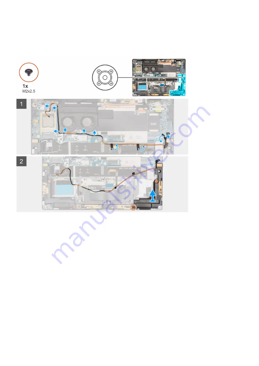
The following images indicate the location of the left speaker and provide a visual representation of the removal procedure.

Steps

1. Disconnect the speaker cable from the connector on the system board.
2. Peel back the adhesive tape that secures the orange WWAN-antenna cable(AUX3) to the system board.
3. Remove the orange WWAN-antenna cable from the routing guides along the system board.
4. Remove the single (M2x2.5) screw from the speaker and lift the left speaker from the computer.

Installing the left speaker

Prerequisites

If you are replacing a component, remove the existing component before performing the installation procedure.

About this task

The following images indicate the location of the left speaker and provide a visual representation of the installation procedure.

Removing and installing components

37

Summary of Contents for Latitude 9330

Page 1: ...Latitude 9330 Service Manual Regulatory Model P35S Regulatory Type P35S001 June 2022 Rev A00 ...

Page 2: ...damage to hardware or loss of data and tells you how to avoid the problem WARNING A WARNING indicates a potential for property damage personal injury or death 2022 Dell Inc or its subsidiaries All rights reserved Dell Technologies Dell and other trademarks are trademarks of Dell Inc or its subsidiaries Other trademarks may be trademarks of their respective owners ...

Page 3: ...lling the SIM card tray 14 Base cover 15 Removing the base cover 15 Installing the base cover 18 Battery 20 Lithium ion battery precautions 20 Removing the battery 21 Installing the battery 21 M 2 solid state drive 22 Removing the M 2 2230 solid state drive 22 Installing the M 2 2230 solid state drive 23 WWAN card 24 Removing the WWAN card 24 Installing the WWAN card 25 Fan 27 Removing the system ...

Page 4: ... the BIOS in Linux and Ubuntu 69 Updating the BIOS using the USB drive in Windows 69 Updating the BIOS from the F12 One Time boot menu 70 System and setup password 70 Assigning a system setup password 71 Deleting or changing an existing system setup password 71 Clearing CMOS settings 72 Clearing BIOS System Setup and System passwords 72 Chapter 5 Troubleshooting 73 Handling swollen Lithium ion bat...

Page 5: ...Chapter 6 Getting help and contacting Dell 79 Contents 5 ...

Page 6: ...ng inside your computer ground yourself by touching an unpainted metal surface such as the metal at the back of the computer While you work periodically touch an unpainted metal surface to dissipate static electricity which could harm internal components CAUTION When you disconnect a cable pull it by its connector or its pull tab not the cable itself Some cables have connectors with locking tabs o...

Page 7: ...ystem and all attached peripherals Disconnect the system and all attached peripherals from AC power Disconnect all network cables telephone and telecommunications lines from the system Use an ESD field service kit when working inside any notebook to avoid electrostatic discharge ESD damage After removing any system component carefully place the removed component on an anti static mat Wear shoes wi...

Page 8: ...atic mat your wrist strap should be snug and the bonding wire should be connected to the mat and to any bare metal on the system being worked on Once deployed properly service parts can be removed from the ESD bag and placed directly on the mat ESD sensitive items are safe in your hand on the ESD mat in the system or inside a bag Wrist Strap and Bonding Wire The wrist strap and bonding wire can be...

Page 9: ... When transporting ESD sensitive components such as replacement parts or parts to be returned to Dell it is critical to place these parts in anti static bags for safe transport After working inside your computer About this task CAUTION Leaving stray or loose screws inside your computer may severely damage your computer Steps 1 Replace all screws and ensure that no stray screws remain inside your c...

Page 10: ... them in a screw storage box This is to ensure that the correct number of screws and correct screw type is restored when the component is replaced NOTE Some computers have magnetic surfaces Ensure that the screws are not left attached to such surfaces when replacing a component NOTE Screw color may vary with the configuration ordered Table 1 Screw list Component Screw type Quantity Screw image Bas...

Page 11: ...5 8 5 Power button M1 6x2 3 2 WLAN LTE antenna module M1 6x2 3 2 Keyboard M1 2x1 3 M1 2x1 4 37 1 Customer Replaceable Units CRU and Field Replaceable Units FRU list Table 2 CRU FRU list Latitude 9330 CRU component FRU component SIM card tray Base cover M 2 solid state drive WWAN card System fan Heat sink Display assembly Removing and installing components 11 ...

Page 12: ... component Battery Left speaker Right speaker WLAN antenna module System board Power button with FPR Keyboard Palm rest assembly Major components of Latitude 9330 The following image shows the major components of Latitude 9330 12 Removing and installing components ...

Page 13: ...dule 16 System fans 17 Heat sink 18 WWAN card 19 WWAN card shield cover NOTE Dell provides a list of components and their part numbers for the original system configuration purchased These parts are available according to warranty coverages purchased by the customer Contact your Dell sales representative for purchase options SIM card tray Removing the SIM card About this task The following images ...

Page 14: ...e system 4 Remove the Micro SIM from the SIM card tray 5 Slide the SIM card tray back into the slot on the system Installing the SIM card tray Prerequisites If you are replacing a component remove the necessary component before the installation procedure About this task The following images provide a visual representation of the SIM card tray installation procedure 14 Removing and installing compo...

Page 15: ...n and place the Micro SIM card in the dedicated slot on the SIM card tray 5 Slide the SIM card tray back into the slot on the system Base cover Removing the base cover Prerequisites 1 Follow the procedure in Before working inside your computer About this task The following images indicate the location of the base cover and provide a visual representation of the removal procedure Removing and insta...

Page 16: ...16 Removing and installing components ...

Page 17: ...rrows to release the base cover from the palm rest and keyboard assembly CAUTION Do not pull on the base cover from the top side immediately after prying it open from the indents This will cause damage to the base cover Continue with the steps described below to loosen all the hooks that secure the base cover to the system before removing the base cover 3 Firmly hold the left side and the right si...

Page 18: ... your computer over and press the power button for 5 seconds to drain the flea power Installing the base cover Prerequisites About this task The following images indicate the location of the base cover and provide a visual representation of the installation procedure 18 Removing and installing components ...

Page 19: ...Removing and installing components 19 ...

Page 20: ...ter from the system and operate the computer solely on battery power the battery is fully discharged when the computer no longer turns on when the power button is pressed Do not crush drop mutilate or penetrate the battery with foreign objects Do not expose the battery to high temperatures or disassemble battery packs and cells Do not apply pressure to the surface of the battery Do not bend the ba...

Page 21: ...powered on it prompts for the Real Time Clock RTC reset When the RTC reset cycle occurs the computer restarts several times and then an error message is displayed Time of day not set Enter the BIOS when this error appears and set the date and time on your computer to resume normal functionality About this task The following image indicates the location of the battery and provides a visual represen...

Page 22: ...llow the procedure in After working inside your computer M 2 solid state drive Removing the M 2 2230 solid state drive Prerequisites 1 Follow the procedure in Before working inside your computer 2 Remove the base cover About this task The following images indicate the location of the M 2 2230 solid state drive and provide a visual representation of the removal procedure 22 Removing and installing ...

Page 23: ...s the solid state drive to the system board 4 Slide and remove the solid state drive off the system board Installing the M 2 2230 solid state drive Prerequisites If you are replacing a component remove the existing component before performing the installation procedure About this task The following images indicate the location of the M 2 2230 solid state drive and provide a visual representation o...

Page 24: ... the system board 4 Using the alignment post place the solid state drive shielding cover over the solid state drive Next steps 1 Install the base cover 2 Follow the procedure in After working inside your computer WWAN card Removing the WWAN card Prerequisites 1 Follow the procedure in Before working inside your computer 2 Remove the SIM card 3 Remove the base cover About this task The following im...

Page 25: ... NOTE When replacing the system board the thermal pad sticker underneath the WWAN card must be transferred to the replacement system board NOTE For systems shipped with a 4G WWAN card when replacing the system board the WWAN card support frame must be transferred to the replacement system board Installing the WWAN card Prerequisites If you are replacing a component remove the existing component be...

Page 26: ...ngle into the WWAN card slot 3 Connect the antenna cables to the connectors on the WWAN card 4 Align and place the WWAN card shielding cover on the system board and WWAN card 5 Push down on the WWAN card with the WWAN card bracket and replace the single M2x2 5 screw Next steps 1 Install the base cover 2 Install the SIM card 3 Follow the procedure in After working inside your computer 26 Removing a...

Page 27: ...e connector on the system board 2 Disconnect the right fan FPC from the connector on the system board 3 Remove the two M2x2 5 screws that secure the fan to the system board 4 Lift the fan off the computer Installing the system fan Prerequisites If you are replacing a component remove the existing component before performing the installation procedure About this task The following images indicate t...

Page 28: ...orking inside your computer Heat sink Removing the heat sink Prerequisites 1 Follow the procedure in Before working inside your computer CAUTION Do not touch the heat transfer areas on the heat sink The oils in your skin can reduce the heat transfer capability of the thermal grease NOTE The heat sink may become hot during normal operation Allow sufficient time for the heat sink to cool before you ...

Page 29: ...WWAN antenna cable AUX3 from the bottom side of the CPU shielding cover 2 Peel back the foil from the top and bottom side of the CPU shielding cover NOTE After peeling back the foil sheet from the top and bottom side of the shielding cover pry open the cover using the tabs located at its left and bottom corner to remove the cover from the system Removing and installing components 29 ...

Page 30: ...talling the heat sink Prerequisites CAUTION Incorrect alignment of the heat sink can damage the system board and the processor NOTE If either the system board or the heat sink is replaced use the thermal pad or thermal paste provided in the kit to ensure that there is thermal conductivity About this task The following images indicate the location of the heat sink and provide a visual representatio...

Page 31: ...rs on the heat sink tighten the three M2x2 5 screws to secure the heat sink to the system board 3 Place the CPU shielding cover over the CPU NOTE When installing the heatsink shielding cover make sure that the two thermal pads are firmly attached on the underside of the cover If any of the two thermal pads gets detached adhere it back to the cover Removing and installing components 31 ...

Page 32: ...erequisites 1 Follow the procedure in Before working inside your computer 2 Remove the SIM card 3 Remove the base cover About this task The following images indicate the location of the display assembly and provide a visual representation of the removal procedure NOTE The display assembly is a Hinge Up Design HUD assembly and cannot be further disassembled once it is removed from the chassis If an...

Page 33: ...Removing and installing components 33 ...

Page 34: ...system board and disconnect the camera cable 3 Using the pull tab disconnect the display cable and camera cable from the connector on the system board 4 Remove the display and camera cables from the routing guides on the palm rest and keyboard assembly 5 Remove the two M2 5x3 screws from the left hinge and fold back the left hinge 34 Removing and installing components ...

Page 35: ...s to 45 degrees and slide the system put from the display assembly Installing the display assembly Prerequisites If you are replacing a component remove the existing component before performing the installation procedure About this task The following images indicate the location of the display assembly and provide a visual representation of the installation procedure Removing and installing compon...

Page 36: ...le to the system board 6 Connect and adhere the camera cable to the system board 7 Place the display cable bracket over the display cable connector and install the two M2x2 5 screws to secure it to the system board Next steps 1 Install the base cover 2 Install the SIM card 3 Follow the procedure in After working inside your computer Speakers Removing the left speaker Prerequisites 1 Follow the pro...

Page 37: ...ystem board 3 Remove the orange WWAN antenna cable from the routing guides along the system board 4 Remove the single M2x2 5 screw from the speaker and lift the left speaker from the computer Installing the left speaker Prerequisites If you are replacing a component remove the existing component before performing the installation procedure About this task The following images indicate the location...

Page 38: ...e WWAN antenna cable to the palm rest and keyboard assembly 5 Connect the speaker cable to the connector on the system board Next steps 1 Install the battery 2 Install the WWAN card 3 Install the base cover 4 Install the SIM card 5 Follow the procedure in After working inside your computer Removing the right speaker Prerequisites 1 Follow the procedure in Before working inside your computer 2 Remo...

Page 39: ...LAN antenna cables from their connectors on the system board 5 Remove the speaker green P sensor cable gray P sensor cable and the WLAN antenna cables from the routing guides on the system board and the right speaker 6 Remove the single M2x2 5 screw that secures the speaker to the palm rest and keyboard assembly and remove the right speaker from the computer Installing the right speaker Prerequisi...

Page 40: ...ble gray P sensor cable and the WLAN antenna cables to their connectors on the system board 5 Place the P sensor bracket on the system board and replace the single M2x2 5 screw to secure it in place 6 Place the WLAN bracket on the system board and replace the single M2x2 5 screw to secure it in place 7 Connect the speaker cable to the connector on the system board Next steps 1 Install the battery ...

Page 41: ...racket and remove the P sensor bracket from the computer 2 Remove the single M2x2 5 screw from the WLAN bracket and remove the WLAN bracket from the computer 3 Disconnect the green P sensor cable gray P sensor cable and the WLAN antenna cables from their connectors on the system board 4 Remove the green P sensor cable gray P sensor cable and the WLAN antenna cables from the routing guides on the s...

Page 42: ...on the palm rest and keyboard assembly 2 Replace the three M1 6x2 3 screws to secure the WLAN antenna module to the palm rest and keyboard assembly 3 Route the green P sensor cable gray P sensor cable and the WLAN antenna cables through the routing guides on the system board 4 Connect the green P sensor cable gray P sensor cable and the WLAN antenna cables to their connectors on the system board 5...

Page 43: ...Prerequisites 1 Follow the procedure in Before working inside your computer 2 Remove the SIM card 3 Remove the base cover 4 Remove the WWAN card 5 Remove the battery 6 Remove the solid state drive 7 Remove the heat sink About this task The following images indicate the location of the system board assembly and provide a visual representation of the removal procedure Removing and installing compone...

Page 44: ...44 Removing and installing components ...

Page 45: ...e single M2x2 5 screw from the fingerprint reader bracket and remove the fingerprint reader bracket from the computer 5 Disconnect the display cable camera cable and speaker cable from the connectors on the system board 6 Disconnect the green P sensor cable gray P sensor cable WLAN antenna cables Darwin cables from their connectors on the system board NOTE To disconnect the Darwin cables from the ...

Page 46: ...rom the computer 11 Remove the three M2x3 5 screws from the right Type C bracket and remove the right Type C bracket from the computer 12 Remove the two M2x2 5 screws that secure the system board to the palm rest and keyboard assembly 13 Lift and remove the system from the computer NOTE To prevent obstructions while lifting the system board technicians should clear the area around the system board...

Page 47: ...Removing and installing components 47 ...

Page 48: ...te the display cable and camera cable through the routing guides on the palm rest and keyboard assembly 7 Route the WWAN antenna cable through the routing guides on the system board 8 Connect the fingerprint reader cable LED board FFC Touch pad FFC and USH board FFC to the connectors on the system board 9 Connect the green P sensor cable gray P sensor cable WLAN antenna cables Darwin cables to the...

Page 49: ... card 5 Remove the battery 6 Remove the heat sink 7 Remove the system board NOTE The system board can be removed with the heat sink attached in order to simplify the procedure and preserve the thermal bond between the system board and heat sink About this task The following images indicate the location of the power button and provide a visual representation of the removal procedure Steps 1 Remove ...

Page 50: ...er button assembly on the palm rest and keyboard assembly 2 Replace the two M1 6x2 3 screws to secure the power button assembly to the palm rest and keyboard assembly Next steps 1 Install the system board 2 Install the heat sink 3 Install the battery 4 Install the WWAN card 5 Install the base cover 6 Install the SIM card 7 Follow the procedure in After working inside your computer Keyboard Removin...

Page 51: ... and preserve the thermal bond between the system board and heat sink About this task The following images indicate the location of the keyboard and provide a visual representation of the removal procedure Steps 1 Peel back the foil covering the WWAN LTE antenna module 2 Disconnect the keyboard FFC from the connector on the touchpad 3 Peel back the graphite mylar covering the keyboard to access th...

Page 52: ...board Prerequisites If you are replacing a component remove the existing component before performing the installation procedure About this task The following images indicate the location of the keyboard and provide a visual representation of the installation procedure Steps 1 Align and place the keyboard on the palm rest assembly 2 Replace the thirty seven M1 2x1 3 screws and the single M1 2x1 4 t...

Page 53: ...Palm rest Prerequisites 1 Follow the procedure in Before working inside your computer 2 Remove the SIM card 3 Remove the base cover 4 Remove the solid state drive 5 Remove the WWAN card 6 Remove the display assembly 7 Remove the battery 8 Remove the fan 9 Remove the heat sink 10 Remove the left speaker 11 Remove the right speaker 12 Remove the system board NOTE The system board can be removed with...

Page 54: ...e display assembly 11 Install the WWAN card 12 Install the solid state drive 13 Install the base cover 14 Install the SIM card 15 Follow the procedure in After working inside your computer Palmrest Palm rest Prerequisites 1 Follow the procedure in Before working inside your computer 2 Remove the SIM card 3 Remove the base cover 4 Remove the solid state drive 5 Remove the WWAN card 6 Remove the dis...

Page 55: ...the power button 15 Remove the keyboard About this task Next steps 1 Install the keyboard 2 Install the power button 3 Install the WLAN antenna module 4 Install the system board 5 Install the right speaker 6 Install the left speaker 7 Install the heat sink 8 Install the fan 9 Install the battery 10 Install the display assembly 11 Install the WWAN card 12 Install the solid state drive 13 Install th...

Page 56: ...rivers and downloads When troubleshooting downloading or installing drivers it is recommended that you read the Dell Knowledge Based article Drivers and Downloads FAQ 000123347 3 56 Drivers and downloads ...

Page 57: ...ling base devices Entering BIOS setup program About this task Turn on or restart your computer and press F2 immediately Navigation keys NOTE For most of the System Setup options changes that you make are recorded but do not take effect until you restart the system Table 3 Navigation keys Keys Navigation Up arrow Moves to the previous field Down arrow Moves to the next field Enter Selects a value i...

Page 58: ...ervice Code Displays the express service code of the computer Ownership Tag Displays the ownership tag of the computer Signed Firmware Update Displays whether the signed firmware update is enabled Default Enabled Battery Displays the battery health information Primary Displays the primary battery Battery Level Displays the battery level Battery State Displays the battery state Health Displays the ...

Page 59: ...the native resolution of the computer Video BIOS Version Displays the video BIOS version of the computer Audio Controller Displays the audio controller information of the computer Bluetooth Device Displays whether a Bluetooth device is installed in the computer Pass Through MAC Address Displays the MAC address of the video pass through Cellular Device Displays if a SIM card is installed on the com...

Page 60: ...rbolt Technology feature and associated ports and adapters Default ON Enable Thunderbolt Boot Support Enables or disables Thunderbolt adapter features during pre boot Default OFF Enable Thunderbolt and PCIe behind TBT pre boot modules Enables or disables the setting that allows PCIe devices that are connected via a Thunderbolt adapter Default OFF Disable USB PCIE Tunneling Enables or disables Disa...

Page 61: ...s running on battery power Default 50 Brightness on AC power Sets the screen brightness when the computer is running on AC power Default 100 Touch Screen Enables or disables the touch screen for the OS NOTE The touch screen will always work in the BIOS setup irrespective of this setting Full Screen Logo Enabled or disabled the computer to display full screen logo if the image match screen resoluti...

Page 62: ...rged maximizes battery health while still supporting heavy use during the work day Default OFF Peak Shift Enables the computer to run on battery during peak power usage hours Default OFF Thermal Management Sets cooling fan and processor heat management to adjust system performance noise and temperature By default Optimized is selected USB Wake Support Wake on Dell USB C Dock Enables connecting a D...

Page 63: ...he TPM for storing owner data Default ON SHA 256 Enables or disables the BIOS and the TPM to use the SHA 256 hash algorithm to extend measurements into the TPM PCRs during BIOS boot Default ON Clear Enables or disables the computer to clear the PTT owner information and returns the PTT to the default state Default OFF TPM State Enables or disables the TPM This is the normal operating state for the...

Page 64: ...s the administrator password sometimes called the setup password The administrator password enables several security features Password Configuration Upper Case Letter When enabled password must contain at least one upper case letter Default OFF Upper Case Letter When enabled password must contain at least one lower case letter Default OFF Digit When enabled password must contain at least one digit...

Page 65: ...ME corruption or a hardware issue The recovery image must exist on an unencrypted partition on the drive BIOS Downgrade Allow BIOS Downgrade Controls flashing of the system firmware to previous revisions Default ON SupportAssist OS Recovery SupportAssist OS Recovery Enables or disables the boot flow for SupportAssist OS Recovery tool in the event of certain system errors Default ON BIOSConnect BIO...

Page 66: ...e Fn lock option Default ON Lock Mode Default Lock Mode Secondary Lock Mode Secondary If this option is selected the F1 F12 keys scan the code for their secondary functions Keyboard Illumination Keyboard Illumination Configures the operating mode of the keyboard illumination feature By default Bright is selected Keyboard Backlight Timeout on AC Keyboard Backlight Timeout on AC Configures the timeo...

Page 67: ...ress Pass Through MAC Address Pass Through Replaces the external NIC MAC address in a supported dock or dongle with the selected MAC address from the computer By default System Unique MAC Address is selected Sign of Life Early Logo Display Displays Logo Sign of Life Default ON Collaboration Touchpad Enable or disable collaboration touchpad Table 17 System setup options Virtualization menu Virtuali...

Page 68: ...le Intel Turbo Boost Technology Enabled or disabled the Intel TurboBoost mode of the processor If enabled the Intel TurboBoost driver increases the performance of the CPU or graphics processor Default ON Intel Hyper Threading Technology Enable Intel Hyper Threading Technology Enabled or disabled the Intel Hyper Threading mode of the processor If enabled the Intel Hyper Threading increases the effi...

Page 69: ... on screen instructions For more information search in the Knowledge Base Resource at www dell com support Updating the BIOS in Linux and Ubuntu To update the system BIOS on a computer that is installed with Linux or Ubuntu see the knowledge base article 000131486 at www dell com support Updating the BIOS using the USB drive in Windows About this task CAUTION If BitLocker is not suspended before u...

Page 70: ...ate your BIOS from the F12 One Time boot menu you need the following USB drive formatted to the FAT32 file system key does not have to be bootable BIOS executable file that you downloaded from the Dell Support website and copied to the root of the USB drive AC power adapter that is connected to the computer Functional computer battery to flash the BIOS Perform the following steps to perform the BI...

Page 71: ... the changes as prompted by the pop up message 5 Press Y to save the changes The computer restarts Deleting or changing an existing system setup password Prerequisites Ensure that the Password Status is Unlocked in the System Setup before attempting to delete or change the existing System and or Setup password You cannot delete or change an existing System or Setup password if the Password Status ...

Page 72: ... one minute 4 Connect the battery cable to the system board 5 Replace the base cover Clearing BIOS System Setup and System passwords About this task To clear the system or BIOS passwords contact Dell technical support as described at www dell com contactdell NOTE For information on how to reset Windows or application passwords refer to the documentation accompanying Windows or your application 72 ...

Page 73: ...ot bend the battery Do not use tools of any type to pry on or against the battery If a battery gets stuck in a device as a result of swelling do not try to free it as puncturing bending or crushing a battery can be dangerous Do not attempt to reassemble a damaged or swollen battery into a laptop Swollen batteries that are covered under warranty should be returned to Dell in an approved shipping co...

Page 74: ...sues error codes are displayed Note the error code and validation number and contact Dell Built in self test BIST M BIST M BIST Built In Self Test is the system board s built in self test diagnostics tool that improves the diagnostics accuracy of system board embedded controller EC failures NOTE M BIST can be manually initiated before POST Power On Self Test How to run M BIST NOTE M BIST must be i...

Page 75: ...s like flickering distortion clarity issues fuzzy or blurry image horizontal or vertical lines color fade etc it is always a good practice to isolate the LCD screen by running the Built In Self Test BIST How to invoke LCD BIST Test 1 Power off the Dell laptop 2 Disconnect any peripherals that are connected to the laptop Connect only the AC adapter charger to the laptop 3 Ensure that the LCD screen...

Page 76: ...ory modules among the slots If problem persists replace the memory module 2 5 Invalid memory installed Reset and swap memory modules among the slots If problem persists replace the memory module 2 6 System board Chipset Error Replace the system board 2 7 LCD failure SBIOS message Replace the LCD module 2 8 LCD failure EC detection of power rail failure Replace the system board 3 1 CMOS battery fai...

Page 77: ...sues that may occur before your computer boots to the operating system It enables you to diagnose hardware issues repair your computer back up your files or restore your computer to its factory state You can also download it from the Dell Support website to troubleshoot and fix your computer when it fails to boot into their primary operating system due to software or hardware failures For more inf...

Page 78: ...attery is removed For your safety and to protect the sensitive electronic components in your computer you are requested to drain residual flea power before removing or replacing any components in your computer Draining residual flea power also known as a performing a hard reset is also a common troubleshooting step if your computer does not power on or boot into the operating system To drain resid...

Page 79: ...ce Tag or Express Service Code at www dell com support For more information on how to find the Service Tag for your computer see Locate the Service Tag on your computer Dell knowledge base articles for a variety of computer concerns 1 Go to www dell com support 2 On the menu bar at the top of the Support page select Support Knowledge Base 3 In the Search field on the Knowledge Base page type the k...

Reviews: