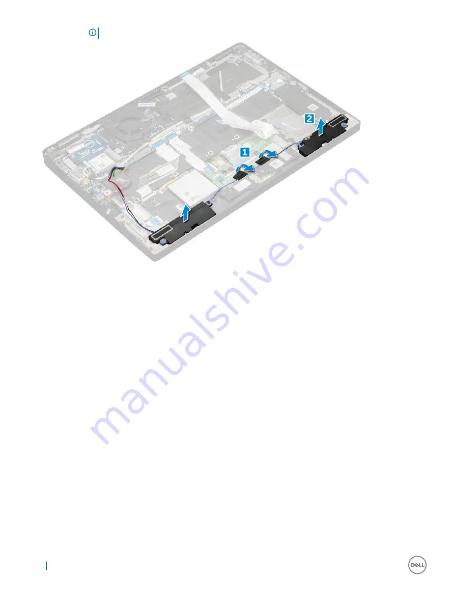
background image

NOTE: 

You can use a plastic scribe to lift the speaker module from the computer.

Installing the speaker module

Place the speaker module into the slots on the computer.

Route the speaker cable through the routing channel and secure it with the tapes.

Connect the speaker cable to the connector on the system board.

Connect the LED cable to the connector on the palm rest.

Install the:

a

power board

b

battery

c

base cover

d

Micro SD

Follow the procedure in 

After working inside your computer

.

Fingerprint Board

Removing the fingerprint reader board

Follow the procedure in 

Before working inside your computer

.

Remove:

a

Micro SD

b

base cover

c

battery

To remove the fingerprint reader board:

a Lift the coin cell battery affixed to the speaker cables [1].

18

Removing and installing components

Summary of Contents for Latitude 7389

Page 1: ...Dell Latitude 7389 2 in 1 Owner s Manual Regulatory Model P29S Regulatory Type P29S001 ...

Page 2: ...amage to hardware or loss of data and tells you how to avoid the problem WARNING A WARNING indicates a potential for property damage personal injury or death 2017 Dell Inc or its subsidiaries All rights reserved Dell EMC and other trademarks are trademarks of Dell Inc or its subsidiaries Other trademarks may be trademarks of their respective owners 2017 08 Rev A00 ...

Page 3: ...e cover 10 Installing the base cover 11 Battery 11 Removing the battery 11 Installing battery 12 PCIe Solid State Drive SSD 12 Removing the NVMe SSD card 12 Installing the NVMe SSD 13 WLAN card 13 Removing the WLAN card 13 Installing the WLAN card 14 WWAN card 14 Removing the WWAN card 14 Installing the WWAN card 15 Power board 15 Removing the power board 15 Installing the power board 16 Speaker 1...

Page 4: ...ng keyboard assembly 33 Palmrest 34 Replacing palm rest 34 3 Technology and components 36 USB features 36 USB 3 0 USB 3 1 Gen 1 SuperSpeed USB 36 Speed 36 Applications 37 Compatibility 38 HDMI 1 4 38 HDMI 1 4 Features 38 Advantages of HDMI 38 4 System specifications 40 System specifications 40 Processor specifications 40 Display specifications 41 Memory 41 Video specifications 41 Audio specificati...

Page 5: ...pport screen options 57 Wireless screen options 57 Maintenance screen options 57 System logs screen options 58 Updating the BIOS in Windows 58 System and setup password 59 Assigning a system password and setup password 59 Deleting or changing an existing system and or setup password 59 6 Software 61 Supported operating systems 61 Downloading drivers 61 Device drivers 61 Display Adapter 61 USB driv...

Page 6: ... or by periodically touching an unpainted metal surface that is grounded to ground yourself before you touch the computer to perform any disassembly tasks CAUTION Handle components and cards with care Do not touch the components or contacts on a card Hold a card by its edges or by its metal mounting bracket Hold a component such as a processor by its edges not by its pins CAUTION When you disconne...

Page 7: ...t the same time as touching a connector on the back of the computer 8 Remove any installed ExpressCards or Smart Cards from the appropriate slots After working inside your computer After you complete any replacement procedure ensure that you connect external devices cards and cables before turning on your computer CAUTION To avoid damage to the computer use only the battery designed for this parti...

Page 8: ...lid State Drive SSD WLAN card WWAN card Power board Speaker Fingerprint Board LED Board Smart Card Cage Heat Sink Display Assembly System Board Real time clock RTC Keyboard Palmrest Screw size list Table 1 Latitude 7389 Screw size list Component M 2 5 x 2 5L M 2 5 x 4 0L M 2 0 x 3 0L M 2 x 2L M 2 0 x 2L M 2 x 1 7L M 2 x 4L M 2 5 x 5 Hinge bracket 6 G senser 1 Lcm frame 2 Hinge bracket 4 1 Logic up...

Page 9: ...w driver is for screws 0 1 and the 1 screw driver is for screws 2 4 Micro Secure Digital SD Card Removing the Micro Secure Digital SD Card 1 Follow the procedure in Before working inside your computer 2 Press in on the Micro SD card to release it from the computer 3 Slide the Micro SD card out of the computer Installing the Micro Secure Digital SD Card 1 Slide the Micro SD into the slot until it c...

Page 10: ...on the micro SIM card tray 2 Use a scribe to pull the micro SIM card tray 3 If a micro SIM card is available remove the micro SIM card from the micro SIM card tray Base cover Removing the base cover 1 Follow the procedure in Before working inside your computer 2 Loosen the M2 5 x 5 0 captive screws that secure the base cover to the computer 3 Use a plastic scribe to pry the base cover starting fro...

Page 11: ...mputer Battery Removing the battery 1 Follow the procedure in Before working inside your computer 2 Remove a MicroSD card b Base cover 3 To remove the battery a Lift the ribbon and disconnect the battery cable from the connector on the system board 1 b Remove the M2 0 x 4 L screws that secure the battery to the computer 2 NOTE The image displayed is for reference only Some components location and ...

Page 12: ...ter PCIe Solid State Drive SSD Removing the NVMe SSD card 1 Follow the procedure in Before working inside your computer 2 Remove a MicroSD card b base cover c battery NOTE You need not remove the battery instead you can disconnect the battery cable from the system board 3 To remove the NVMe SSD card a Loosen the M2 0 x 3 0 screws that secure SSD thermal bracket 1 b Lift the thermal bracket from th...

Page 13: ...d b base cover c MicroSD card 5 Follow the procedure in After working inside your computer WLAN card Removing the WLAN card 1 Follow the procedure in Before working inside your computer 2 Remove a MicroSD card b base cover c battery NOTE You need not remove battery instead you can disconnect the battery cable from the system board 3 To remove the WLAN card a Remove the M2 0 x 3 0 screw that secure...

Page 14: ...ard to the computer 4 Install the a battery NOTE If you have not removed the battery then you must connect the battery cable to the system board b base cover c MicroSD card 5 Follow the procedure in After working inside your computer WWAN card Removing the WWAN card 1 Follow the procedure in Before working inside your computer 2 Remove a MicroSD card b base cover c battery NOTE You need not remove...

Page 15: ...e not removed the battery then you must connect the battery cable to the system board b base cover c MicroSD card 5 Follow the procedure in After working inside your computer NOTE The IMEI number can also be found on the WWAN card Power board Removing the power board 1 Follow the procedure in Before working inside your computer 2 Remove a MicroSD card b SIM card tray NOTE SIM Card tray is availabl...

Page 16: ...ll the a battery b base cover c MicroSD card 6 Follow the procedure in After working inside your computer Speaker Removing the speaker module 1 Follow the procedure in Before working inside your computer 2 Remove a MicroSD card b base cover c battery d power board 3 To disconnect the cables a Disconnect the and fold back the smart card cable 1 b Disconnect and fold back the LED board for easy acce...

Page 17: ...oard 1 b Un route the speaker cable from the retention clips and remove the tapes that secure the speaker cable 2 5 To remove the speaker module a Un route the speaker cable by removing the tapes near the palm rest 1 b Lift the speaker module from the computer Removing and installing components 17 ...

Page 18: ... the system board 4 Connect the LED cable to the connector on the palm rest 5 Install the a power board b battery c base cover d Micro SD 6 Follow the procedure in After working inside your computer Fingerprint Board Removing the fingerprint reader board 1 Follow the procedure in Before working inside your computer 2 Remove a Micro SD b base cover c battery 3 To remove the fingerprint reader board...

Page 19: ...s affixed to the palm rest and you may need a plastic scribe to lift the fingerprint reader board Installing the fingerprint reader board 1 Install the fingerprint reader board into the slot 2 Place the fingerprint reader bracket on the board 3 Replace the M2 x 3 screw to secure the bracket to the board 4 Connect the fingerprint reader cable to the fingerprint reader board and the USH board 5 Affi...

Page 20: ...touchpad panel 2 c Remove the M2 x 3 screws that secure the LED board 3 d Lift the LED board from the computer 4 Installing the LED board 1 Install the LED board into the slot 2 Replace the M2 x 3 screws to secure the LED board 3 Affix the tape to secure the LED board 4 Connect the LED board cable to the LED board 5 Install the a battery b base cover c SD card 6 Follow the procedure in After worki...

Page 21: ...SD card 3 To disconnect the cables a Disconnect the smart card cable 1 b Disconnect the LED board cable 2 c Peel the SSD thermal pad from the SSD slot 3 NOTE You may need to apply force to peel off the SSD thermal pad 4 To remove the smart card cage a Remove the M2 0 x 1 7 screws that secure the smart card cage to the computer 1 b Lift the smart card cage from the computer 2 Removing and installin...

Page 22: ...LED board on the computer 5 Affix the smart card cable and connect it to the USH board on the computer 6 Install the a SSD card b battery c base cover d Micro SD 7 Follow the procedure in After working inside your computer Heat Sink Removing heat sink assembly 1 Follow the procedure in Before working inside your computer 2 Remove the a Micro SD b base cover c battery 3 To remove the heat sink asse...

Page 23: ... sink to the system board NOTE Tighten the screws on the system board in the order of the callout numbers 1 2 3 4 as indicated on the heat sink 3 Replace the M2 0 x 3 0 screws to secure the fan to the system board 4 Connect the fan cable to the connector on the system board 5 Install the a battery b base cover 6 Follow the procedure in After working inside your computer Display Assembly Removing t...

Page 24: ...es from the routing clips 4 Disconnect the a IR camera and touchscreen cable 1 b Remove the M 2 x 1 7L screws that secure the eDP bracket and lift it away from the computer 2 c Disconnect the eDP cable from the system board 3 d Disconnect th G sensor and eDP cables 4 24 Removing and installing components ...

Page 25: ...play assembly at 270 degrees laptop mode or 90 degrees tablet mode NOTE If the system is used as a laptop then display assembly should be at 270 degrees and for a fully closed tablet configuration the display should be at 90 degrees b Remove the M2 5 x 4 0 screws that secure the display hinge brackets 1 Removing and installing components 25 ...

Page 26: ...ssembly and flip the computer 5 Connect the cables a G sensor and eDP cable b Place the eDP bracket on the eDP cable and replace the M 2 x 1 7L screw on the bracket c IR camera and touch screen cables 6 Route the antenna cables through the routing clips 7 Affix the tapes to secure the antenna cables to the system board 8 Install the a WWAN card b WLAN card c battery d base cover e Micro SD 9 Follo...

Page 27: ... cable b USH cable c LED board cable 4 Disconnect the eDP cable NOTE To disconnect the eDP cable remove the M 2 x 1 7L screws that secure the eDP bracket and lift it away from the computer Disconnect the eDP cable from the system board 5 To release the cables a Flip the coin cell battery to reveal the speaker cable 1 b Disconnect the speaker cable from the system board 2 c Disconnect the power boa...

Page 28: ...ove the system board a Remove the M2 0 x 4L screws from the USB Type C bracket 1 b Lift the USB Type C bracket from the Type C module 2 c Remove the M2 0 x 3 0 screws that secure the system board to the computer 3 d Lift the system board away from the computer 4 28 Removing and installing components ...

Page 29: ... the tapes to secure the antenna cables 6 Connect the power board and the speaker cable to the system board 7 Affix the coin cell battery on the speaker cable 8 Connect the USH board Touchpad board and LED board cables to the system board 1 NOTE If your computer has a WWAN card then SIM card tray installation is a requirement 9 Install the a heatsink module b WWAN card c WLAN card d SSD card e bat...

Page 30: ...AN card g WWAN card h heat sink assembly i system board NOTE RTC is located on the system board and hence system board removal is a requirement 3 Disconnect the RTC cable to release it from the system board Installing real time clock RTC 1 Connect the coin cell battery cable to the system board 2 Install a system board b heat sink module c WWAN card d WLAN card e SSD card f battery g base cover h ...

Page 31: ...dure in Before working inside your computer 2 Remove the a Micro SD b SIM card tray NOTE SIM Card tray is available only if your computer is shipped with a WWAN card c base cover d battery e SSD card f WLAN card g WWAN card h Heatsink assembly i system board 3 Peel and disconnect the cables a LED board cable 1 b SSD thermal pad 2 c keyboard and backlit keyboard cables 3 4 To remove the keyboard a ...

Page 32: ...edure in Before working inside your computer 2 Remove the keyboard 3 Remove the keyboard from the keyboard support tray a Remove the M2 0 x 2 0 screws that secure the keyboard to the keyboard assembly 1 b Lift the keyboard away from the keyboard support tray 2 32 Removing and installing components ...

Page 33: ... the chassis 2 Replace the M2 0 x 3 0 screws that secure the keyboard to the chassis 3 Affix and connect the keyboard and the backlit keyboard cables to the keyboard 4 Affix the LED board cable on the keyboard 5 Affix the SSD thermal pad on the SSD module NOTE If your computer has a WWAN card then SIM card tray installation is a requirement 6 Install the a system baord b heatsink module c WWAN car...

Page 34: ... WLAN card e WWAN card f power board g heat sink assembly h RTC i LED board j speaker k smart card cage l display assembly m system board n keyboard The component you are left with is the palmrest 3 Replace the palmrest 4 Install the a keyboard assembly b system board c display assembly d smart card cage 34 Removing and installing components ...

Page 35: ...eaker f LED board g RTC h heat sink i power board j WLAN card k WWAN card l PCIe SSD m battery n base cover 5 Follow the procedure in After working inside your computer Removing and installing components 35 ...

Page 36: ...or more speed grows by ever faster computing hardware and ever greater bandwidth demands The USB 3 0 USB 3 1 Gen 1 finally has the answer to the consumers demands with a theoretically 10 times faster than its predecessor In a nutshell USB 3 1 Gen 1 features are as follows Higher transfer rates up to 5 Gbps Increased maximum bus power and increased device current draw to better accommodate power hu...

Page 37: ... actual real world maximum Similarly USB 3 0 USB 3 1 Gen 1 connections will never achieve 4 8Gbps We will likely see a real world maximum rate of 400MB s with overheads At this speed USB 3 0 USB 3 1 Gen 1 is a 10x improvement over USB 2 0 Applications USB 3 0 USB 3 1 Gen 1 opens up the laneways and provides more headroom for devices to deliver a better overall experience Where USB video was barely...

Page 38: ...D player or A V receiver and a compatible digital audio and or video monitor such as a digital TV DTV The intended applications for HDMI TVs and DVD players The primary advantage is cable reduction and content protection provisions HDMI supports standard enhanced or high definition video plus multichannel digital audio on a single cable NOTE The HDMI 1 4 will provide 5 1 channel audio support HDMI...

Page 39: ...DMI combines video and multichannel audio into a single cable eliminating the cost complexity and confusion of multiple cables currently used in A V systems HDMI supports communication between the video source such as a DVD player and the DTV enabling new functionality Technology and components 39 ...

Page 40: ...ions Storage options Communication specifications Near field communication NFC specifications Fingerprint reader specifications Ports and connector specifications Touchpad specifications Camera specifications IR camera specifications AC adapter specifications Battery specifications Docking Option Active Pen Physical specifications Environmental specifications System specifications Feature Specific...

Page 41: ... vertical 80 80 degrees Pixel pitch FHD 0 144 mm Memory Your computer supports a maximum of 16 GB of memory Table 3 Memory specifications Type LPDDR3 SDRAM Soldered down memory Minimum Memory Configuration 4 GB 8 GB Maximum Memory Configuration 16 GB Video specifications Feature Specification Type Integrated on system board UMA controller Intel HD Graphics 620 External display support On system eD...

Page 42: ...rea network WLAN wireless wide area network WWAN WiGig Bluetooth 4 1 LE Bluetooth 4 2 Intel HW ready SW depends on OS Windows 10 supports up to 4 1 Near field communication NFC specifications Feature Specification Type Broadcom BCM58102 NFC controller NFC Standard ISO IEC 18092 ISO IEC 21481 ISO IEC 14443 Type A and B Japanese Industrial Standard JIS X 6319 4 and ISO IEC 15693 standards Support NF...

Page 43: ...Memory card reader Micro SD 4 0 Universal Subscriber Identity Module uSIM card WWAN One Docking port USB Type C docking Express Card None Touchpad specifications Feature Specification Active area X axis 90 5 mm 3 56 inches Y axis 50 0 mm 1 97 inches Multi touch Configurable single finger and multi finger gestures Camera specifications Feature Specification Type HD fixed focus Sensor type CMOS sens...

Page 44: ...to 60 Hz Output current 45 W 20V 2 25A Continuous 5 0V 2A Continuous Output current 65 W 20V 3 25A Continuous 15V 3A Continuous 9V 3A Continuous 5V 3A Continuous Output current 90 W 20V 4 5A Continuous 15V 3A Continuous 9V 3A Continuous 5V 3A Continuous Rated output voltage 45 W 20 V DC 5 V DC Rated output voltage 65 W and 90 W 20 V DC 15 V DC 9 V DC 5 V DC Weight 45 W 0 17 kg 0 37 lb 65 W 0 216 k...

Page 45: ...lymer Battery with ExpressCharge 60 WHr Polymer Battery with ExpressCharge 60 WHr Long Life Cycle Polymer Battery 45 WHr Polymer Battery with ExpressCharge Length 238 mm 9 37 inches Width 97 2 mm 3 82 inches Height 4 7 mm 0 19 inch Weight 220 g 0 48 lb Voltage 11 4 VDC Life span 300 discharge per charge cycles 60 WHr Polymer Battery with ExpressCharge Length 238 mm 9 37 inches Width 95 9 mm 3 78 i...

Page 46: ...um coin cell Docking Option Feature Specification Type Dell Dock WD15 Active Pen Feature Specification Type Wacom PCAP technology Physical specifications Feature Specification Front height 0 46 inch 11 79 mm Back height 0 70 inch Narrow border 18 75mm Standard border 19 83 mm Width 12 00 inches 305 1 mm Depth 8 26 inches Narrow border 210 0 mm Standard border 211 0 mm Weight 3 11 lbs 1 41 kg Envir...

Page 47: ...densing Storage 5 to 95 non condensing Altitude maximum Specifications Operating 0 m to 3048 m 0 to 10 000 ft 0 to 40 C 32 to 104 F Non operating 0 m to 10668 m 0 to 35 000 ft Airborne contaminant level G2 or lower as defined by ISA S71 04 1985 System specifications 47 ...

Page 48: ...ent screen options POST behavior screen options Manageability Virtualization support screen options Wireless screen options Maintenance screen options System logs screen options Updating the BIOS in Windows System and setup password Boot menu Press F12 when the Dell logo appears to initiate a one time boot menu with a list of the valid boot devices for the system Diagnostics and BIOS Setup options...

Page 49: ...n Description System Information This section lists the primary hardware features of your computer System Information Displays BIOS Version Service Tag Asset Tag Ownership Tag Ownership Date Manufacture Date Express Service Code the Signed Firmware update enabled by default Memory Information Displays Memory Installed Memory Available Memory Speed Memory Channels Mode Memory Technology DIMM ASize ...

Page 50: ...are enabled by default The options are SATA 2 enabled by default M 2 PCIe SSD 0 enabled by default M 2 PCIe SSD 1 enabled by default SMART Reporting This field controls whether hard drive errors for integrated drives are reported during system startup This technology is part of the SMART Self Monitoring Analysis and Reporting Technology specification This option is disabled by default Enable SMART...

Page 51: ...disabled Security level Secure connect is disabled Security level Display port only is disabled USB PowerShare This field configures the USB PowerShare feature behavior This option allows you to charge external devices using the stored system battery power through the USB PowerShare port This option is disabled by default Audio This field enables or disables the integrated audio controller By defa...

Page 52: ...ls whether the screen is enabled or disabled This option is enabled by default Unobtrusive Mode This option when enabled pressing Fn F7 turns off all light and sound emissions in the system To resume normal operation press Fn F7 again This option is disabled by default Miscellaneous Devices Allows you to enable or disable the following devices Enable Camera enabled by default Enable Secure Digital...

Page 53: ...s are 32 MB 64 MB 128 MB enabled by default Performance screen options Option Description Multi Core Support This field specifies whether the process has one or all cores enabled The performance of some applications improves with the additional cores This option is enabled by default Allows you to enable or disable multi core support for the processor The installed processor supports two cores If ...

Page 54: ...e at which the computer must turn on automatically The options are Disabled Every Day Weekdays Select Days Default setting Disabled USB Wake Support Allows you to enable USB devices to wake the system from Standby NOTE This feature is only functional when the AC power adapter is connected If the AC power adapter is removed during Standby the system setup removes power from all the USB ports to con...

Page 55: ...over a shorter time using Dell s fast charging technology This option is enabled by default Primarily AC use Custom If Custom Charge is selected you can also configure Custom Charge Start and Custom Charge Stop NOTE All charging mode may not be available for all the batteries To enable this option disable the Advanced Battery Charge Configuration option Sleep mode OS Automatic selection enabled by...

Page 56: ...Fn Lock enabled by default Lock Mode Disable Standard enabled by default Lock Mode Enable Secondary Fastboot Allows you to speed up the boot process by bypassing some of the compatibility steps The options are Minimal enabled by default Thorough Auto Extended BIOS POST Time Allows you to create an extra preboot delay The options are 0 seconds enabled by default 5 seconds 10 seconds Full Screen Log...

Page 57: ... feature Trusted Execution disabled by default Wireless screen options Option Description Wireless Switch Allows to set the wireless devices that can be controlled by the wireless switch The options are WWAN GPS on WWAN Module WLAN WiGig Bluetooth All the options are enabled by default NOTE For WLAN and WiGig enable or disable controls are tied together and they cannot be enabled or disabled indep...

Page 58: ...at your computer battery is fully charged and connected to a power outlet NOTE If BitLocker is enabled it must be suspended prior to updating the system BIOS and then re enabled after the BIOS update is completed 1 Restart the computer 2 Go to Dell com support Enter the Service Tag or Express Service Code and click Submit Click Detect Product and follow the instructions on screen 3 If you are unab...

Page 59: ...The password can contain the numbers 0 through 9 Only lower case letters are valid upper case letters are not allowed Only the following special characters are allowed space 3 Type the system password that you entered earlier in the Confirm new password field and click OK 4 Press Esc and a message prompts you to save the changes 5 Press Y to save the changes The computer reboots Deleting or changi...

Page 60: ...The computer reboots 60 System setup ...

Page 61: ...and then click Submit NOTE If you do not have the Service Tag use the auto detect feature or manually browse for your notebook model 4 Click Drivers and Downloads 5 Select the operating system installed on your notebook 6 Scroll down the page and select the driver to install 7 Click Download File to download the driver for your notebook 8 After the download is complete navigate to the folder where...

Page 62: ...USB drivers Verify if the USB drivers are already installed in the system 62 Software ...

Page 63: ...System drivers Verify if the system drivers are already installed in the system continued Software 63 ...

Page 64: ...Storage controller Verify if the storage controller drivers are already installed in the system 64 Software ...

Page 65: ...Audio drivers Verify if the audio drivers are already installed in the system Software 65 ...

Page 66: ...Identifying Camera Under Device Manager expand Imaging devices Network adapter Verify if the network adapter drivers are already installed in the system 66 Software ...

Page 67: ...Software 67 ...

Page 68: ...mputer 2 As the computer boots press the F12 key as the Dell logo appears 3 On the boot menu screen select the Diagnostics option 4 Click the arrow key at the bottom left corner Diagnostics front page is displayed 5 Press the arrow in the lower right corner to go to the page listing The items detected are listed 6 To run a diagnostic test on a specific device press Esc and click Yes to stop the di...

Page 69: ...age found but invalid Real Time Clock RTC reset The Real Time Clock RTC reset function allows you or the service technician to recover the recently launched model Dell Latitude and Precision systems from select No POST No Boot No Power situations You can initiate the RTC reset on the system from a power off state only if it is connected to AC power Press and hold the power button for 25 seconds Th...

Page 70: ... service options Availability varies by country and product and some services may not be available in your area To contact Dell for sales technical support or customer service issues 1 Go to Dell com support 2 Select your support category 3 Verify your country or region in the Choose a Country Region drop down list at the bottom of the page 4 Select the appropriate service or support link based on...

Reviews: