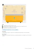
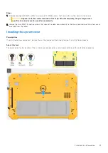
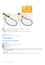
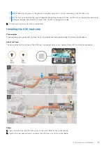
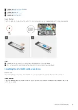
Steps
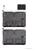
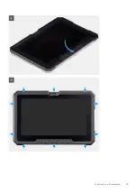
1. Place the tablet on a flat and clean surface and remove the 11 (M2.5x5) screws that secure the display assembly to the
chassis.
CAUTION:
Dispose of all the screws removed in this step. After disassembly, they no longer meet
specifications and cannot be used for reassembly.
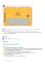
2. Flip the tablet.
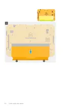
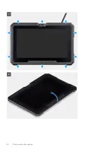
3. Using a plastic scribe, gently pry the edges evenly to unlock the plastic clips that secure the display assembly to the chassis.
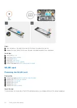
NOTE:
Tip of the plastic scribe should be inserted to avoid damage to the seal on the display assembly and to the clips
that secure the display assembly to the chassis.
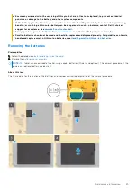
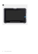
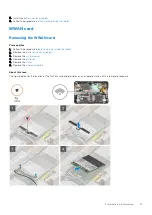
4. Flip the LCD panel by an angle less than 90°.
NOTE:
Ensure not to flip more than 90° angle, as the LCD panel ports and cables are connected to the system board
and may damage the LCD cables.
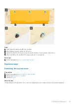
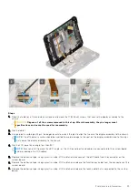
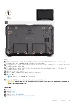
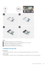
5. Remove the adhesive tape. Using a plastic scribe, lift the latch and disconnect the eDP cable from the connector on the
system board.
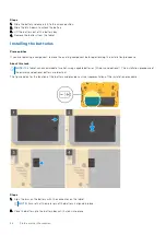
6. Remove the adhesive tape. Using a plastic scribe, lift the latch and release the function key cable from the connector on the
system board.
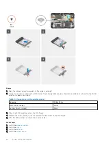
7. Remove the adhesive tape. Using a plastic scribe, lift the latch and release the touch cable that is connected to the system
board.
Field service information
33
Summary of Contents for Latitude 7220EX
Page 20: ...20 Field service information ...
Page 22: ...22 Field service information ...
Page 31: ...Field service information 31 ...
Page 32: ...32 Field service information ...
Page 35: ...Field service information 35 ...
Page 36: ...36 Field service information ...
Page 52: ...52 Field service information ...
Page 54: ...54 Field service information ...
Page 59: ...Field service information 59 ...
Page 62: ...62 Field service information ...


