Steps
1. Remove the singe screw (M2x3) that secures the WLAN antenna cable bracket to the system board.
2. Lift and remove the WLAN antenna cable bracket from the system board.
3. Disconnect the two antenna cables that are connected to the WLAN module on the system board.
4. Remove the singe screw (M2x3) that secures the display cable bracket to the system board. Lift and remove the display
cable bracket from the system board.
5. Open the latch and disconnect the display cable from the connector on the system board.
6. For 2-in-1 systems, disconnect the touch cable from the connector on the system board.
7. Disconnect the power adapter port cable from the connector on the system board.
8. Disconnect the speaker cable and the audio board cable from their connectors on the system board.
9. For systems that are shipped with a USB Type-C port, remove the three screws (M2x4) that secure the USB Type-C
bracket to the system board.
10. For systems that are shipped with a USB Type-C port, lift and remove the USB Type-C bracket from the system board.
11. Remove the two screws (M2x3) that secure the USB Type-A bracket to the system board.
12. Lift and remove the USB Type-A bracket from the system board.
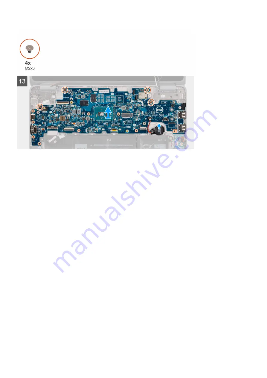
13. For systems that are shipped with a USB Type-C port, remove the four screws (M2x3) that secure the system board to the
computer chassis.
14. For systems that are shipped without a USB Type-C port, remove the six screws (M2x3) that secure the system board to
the computer chassis.
15. Disconnect the coin cell battery cable from the connector on the system board.
16. Pry the coin cell battery to release it from the adhesive. Lift and remove it from the system board.
17. Carefully slide the system board out of the computer.
Installing the system board
Prerequisites
If you are replacing a component, remove the existing component before performing the installation procedure.
About this task
The following images indicate the location of the system board and provide a visual representation of the installation procedure.
Removing and installing components
43
Summary of Contents for Latitude 3120
Page 12: ...Major components of your system 1 Display assembly 12 Removing and installing components ...
Page 14: ...14 Removing and installing components ...
Page 16: ...16 Removing and installing components ...
Page 30: ...30 Removing and installing components ...
Page 32: ...32 Removing and installing components ...
Page 42: ...42 Removing and installing components ...
Page 44: ...44 Removing and installing components ...
Page 50: ...50 Removing and installing components ...


