background image

Removing and Replacing Parts : Dell Inspiron 8100 


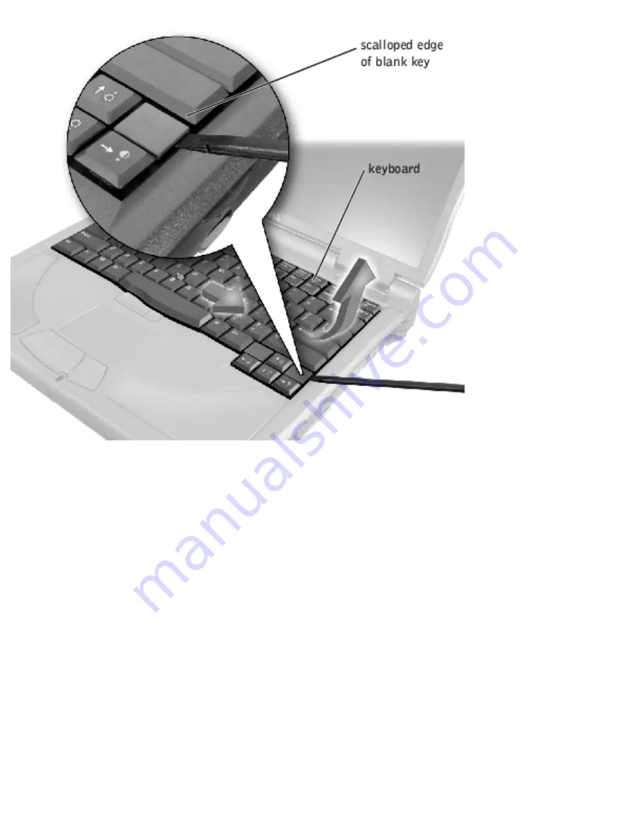
5.  Lift the right end of the keyboard, and slide it slightly to the right to disengage the tabs at the 

left end. 

6.  Pivot the keyboard and balance it upright on the left side of the computer. 

file:///I|/SERVICE%20MANUALS/DELL%20MANUALS/LA...20ok/Inspiron/8000/8000_SERVICE_MAN/remove.htm (16 of 52)6/21/2004 1:07:32 AM

Summary of Contents for Inspiron 8000

Page 1: ...Thank you for purchasing this Factory Service Manual CD DVD from servicemanuals4u com Please check out our eBay auctions for more great deals on Factory Service Manuals servicemanuals4u ...

Page 2: ... User s Guides and click Tell Me How Information in this document is subject to change without notice 2001 Dell Computer Corporation All rights reserved Reproduction in any manner whatsoever without the written permission of Dell Computer Corporation is strictly forbidden Trademarks used in this text Dell Dell TravelLite Inspiron AccessDirect and TrueMobile are trademarks of Dell Computer Corporat...

Page 3: ...Dell Inspiron 8000 than its own August 2001 file I SERVICE 20MANUALS DELL 20MANUALS LA 20ok Inspiron 8000 8000_SERVICE_MAN index htm 2 of 2 6 21 2004 1 07 19 AM ...

Page 4: ...rds that you are not using When possible attach your computer to an electrical outlet when you play CDs and DVDs Playing a CD or DVD uses a lot of battery power Place the computer in standby mode or hibernate mode when you leave the computer unattended for long periods of time Power Conservation Modes Standby Mode Standby mode conserves power by turning off the display and the hard drive after a p...

Page 5: ...on are programmed to activate hibernate mode in the Advanced tab of the Power Options Properties window HINT Some PC Cards may not operate correctly after resuming operation from hibernate mode If you encounter problems with a PC Card reinsert the card or restart your computer To exit hibernate mode press the power button The computer may take a short time to return to its normal operating state P...

Page 6: ...able audible alarms click each Alarm Action button and select Sound alarm The Low battery alarm and Critical battery alarm settings alert you with a message when the battery charge falls below a certain percentage When you receive your computer the Lower battery alarm and Critical battery alarm check boxes are selected Dell recommends that you continue to use these defaults Power Meter Tab The Pow...

Page 7: ...option This setting ensures that your computer does not enter standby mode or hibernate mode when you close lower the display To program these functions click an option from the corresponding pull down menu and then click OK Hibernate Tab The Hibernate tab lets you enable hibernate mode by clicking the Enable hibernate support check box Back to Contents Page file I SERVICE 20MANUALS DELL 20MANUALS...

Page 8: ...Other Technical Problems HINT If you have a problem with an external device see the device documentation or contact the manufacturer Accessing Help Files To access the Tell Me How help file 1 Click the Start button point to Programs User s Guides and then click Tell Me How To access Microsoft Windows 2000 Help 1 Click the Start button and then click Help 2 Click the Search tab 3 Type a word or phr...

Page 9: ...trical outlet Ensure that the electrical outlet is working by testing it with another device such as a lamp Check the AC adapter Be sure that the power cable is firmly inserted into the electrical outlet and the green light on the AC adapter is on Connect the computer directly to an electrical outlet Bypass power protection devices power strips and the extension cable to verify that the computer t...

Page 10: ...attery If you are using a battery to power your computer the battery charge may be depleted Connect the computer to an electrical outlet using the AC adapter and turn on the computer Test the electrical outlet Ensure that the electrical outlet is working by testing it with another device such as a lamp Check the AC adapter Be sure that the power cable is firmly inserted into the electrical outlet ...

Page 11: ...ntegrated Speakers Adjust the Windows volume control Double click the yellow speaker icon in the lower right corner of your screen Be sure that the volume is turned up and that the sound is not muted Check the volume control buttons Press both volume control buttons simultaneously or press Fn End to disable mute or reenable the integrated speakers Reinstall the sound audio driver See Reinstalling ...

Page 12: ...he speaker documentation for self test instructions Move the subwoofer away from the computer or monitor If your external speaker system includes a subwoofer ensure that the subwoofer is at least 60 m 2 ft away from the computer or external monitor Eliminate possible interference Turn off nearby fans fluorescent lights or halogen lamps to check for interference Reinstall the sound audio driver See...

Page 13: ...rical outlet is working by testing it with another device such as a lamp Ensure that the printer is turned on See the documentation supplied with the printer Verify that the printer is recognized by Windows 1 Click the Start button point to Settings and then click Printers If the printer is listed right click the printer icon click Properties and then select the Details tab 2 Ensure that the Print...

Page 14: ...nel 2 In the Control Panel window double click Modems If there are multiple entries for the same modem or modems listed that are not installed delete the entries and restart the computer 3 Click the Diagnostics tab 4 Click the COM port for your modem 5 Click More Info to verify that the modem is communicating with Windows If all commands receive responses the modem is operating properly Scanner Pr...

Page 15: ...e keyboard cable and check the cable connector for bent or broken pins Unexpected Characters Disable the numeric keypad Press the Num Lk key to disable the numeric keypad Verify that the numbers lock light is not lit Drive Problems HINT For information on saving files to a floppy disk see the Tell Me How help file If you cannot save a file to a floppy disk Ensure that Windows recognizes the drive ...

Page 16: ...s recognizes the drive Double click the My Computer icon If the CD drive is not listed perform a full scan with your antivirus software to check for and remove viruses Viruses can sometimes prevent Windows from recognizing the drive Test the drive with another CD Insert another CD to eliminate the possibility that the original CD is defective Clean the disc See the Tell Me How help file for instru...

Page 17: ...ve Test the drive with another DVD Insert another DVD to eliminate the possibility that the original DVD is defective Clean the disc See the Tell Me How help file for instructions If the CD RW drive stops writing HINT If you must disable standby mode to write to a CD RW drive remember to enable standby mode again when you finish writing the CD Disable standby mode in Windows before writing to a CD...

Page 18: ...work connector Green indicates that the network connection is active If the status light is not green try replacing the network cable Amber indicates that the network card driver is loaded and the card is detecting activity Restart the computer Try to log on to the network again Contact your network administrator Verify that your network settings are correct and that the network is functioning Win...

Page 19: ...Select the program that you want to remove 4 Click Add Remove and follow the prompts on the screen 5 See the program documentation for installation instructions Windows 2000 1 Click the Start button point to Settings and then click Control Panel 2 Double click the Add Remove Programs icon 3 Select the program that you want to remove 4 Click Change Remove and follow the prompts on the screen 5 See ...

Page 20: ...ets Wet CAUTION Perform this procedure only after you are certain that it is safe to do so If the computer is connected to an electrical outlet Dell recommends that you turn off AC power at the circuit breaker before attempting to remove the power cables from the electrical outlet Use the utmost caution when removing wet cables from a live power source 1 Turn off the computer disconnect the AC ada...

Page 21: ...15 Turn on the computer and verify that it is working properly If the computer does not start or if you cannot identify the damaged components contact Dell for technical assistance See Contacting Dell in the Dell Solutions Guide that came with your computer for contact information If You Drop or Damage Your Computer 1 Save and close any open files exit any open programs and shut down the computer ...

Page 22: ...t Send an e mail message to Dell about your problem you can expect to receive an e mail message from Dell within hours Call Dell If you cannot solve your problem using the Dell support website or e mail service contact Dell for technical assistance See Contacting Dell in the Dell Solutions Guide that came with your computer for contact information Back to Contents Page file I SERVICE 20MANUALS DEL...

Page 23: ...l Drives Microprocessor Microprocessor type Intel Mobile Pentium III or Mobile Celeron L1 cache 32 KB internal L2 cache 128 KB or 256 KB Math coprocessor internal to microprocessor System Information System chip set Intel 815e Data bus width 64 bits DRAM bus width 64 bits Microprocessor address bus width 32 bits Flash EPROM 4 Mb Graphics bus 64 bit AGP 4X bus file I SERVICE 20MANUALS DELL 20MANUAL...

Page 24: ...128 and 256 MB 3 3 V SDRAM SODIMMS Standard memory 64 MB non ECC Maximum memory 512 MB non ECC Memory clock speed 100 MHz Memory access time CL2 or CL3 CL2 and CL3 indicate a CAS latency of two and three clocks respectively Ports and Connectors Serial 9 pin connector 16550C compatible 16 byte buffer connector Parallel unidirectional standard AT bidirectional or ECP connector Video VGA connector Au...

Page 25: ...rs optional factory configurable RJ 11 and RJ 45 ports for mini PCI modem network controller IEEE 1394 4 pin serial connector Video Video type 128 bit hardware accelerated video support Data bus 4X AGP Video controller ATI Mobility M4 orNVIDIA GeForce2 Go Video memory 8 MB standard 16 MB and 32 MB maximum LCD interface LVDS TV support NTSC or PAL in S video and composite modes Audio Audio controll...

Page 26: ...d Number of keys 87 U S Canada and locations that use traditional Chinese 88 Europe 90 Japan Key travel 2 7 0 4 mm 0 11 0 016 inch Key spacing 19 05 0 3 mm 0 75 inch 0 012 inch Layout QWERTY AZERTY Kanji Touch Pad Interface PS 2 compatible X Y position resolution graphics table mode 240 cpi Size Thickness 2 00 mm 0 08 inch at highest component Width 64 88 mm 2 55 inch Height 48 88 mm 1 92 inch rec...

Page 27: ...Size protrudes 0 5 mm higher than surrounding key caps Power Supply voltage 5 V 0 5 VDC Supply current 25 mA maximum operating current for track stick and touch pad combined ESD in accordance with IEC 801 2 Modem Data Fax modem optional 56K V 90 mini PCI card modem Data Fax NIC optional 10 100 LAN 56K V 90 mini PCI card modem Battery Type 8 cell lithium ion dual battery support is available via th...

Page 28: ...º to 45ºC 32º to 113ºF Storage 20º to 60ºC 4º to 140ºF AC Adapter Input voltage 90 to 135 VAC and 164 to 264 VAC Input current maximum 1 5 A Input frequency 40 to 63 Hz Output current 4 5 A maximum 4 second pulse 3 5 A continuous Rated output voltage 20 VDC Dimensions Height 27 94 mm 1 1 inches Width 58 42 mm 2 3 inches Depth 133 85 mm 5 25 inches Weight with cables 0 4 kg 0 9 lb Temperature range...

Page 29: ...m that simulates user environment Storage 1 3 GRMS using a random vibration spectrum that simulates air truck shipment Maximum shock Operating 1 524 cm sec 60 inches sec equal to a half sine pulse width of 2 ms Storage 2 03 m sec 80 inches sec less than or equal to a pulse width of 2 ms Altitude maximum Operating 15 2 to 3048 m 50 to 10 000 ft Storage 15 2 to 10 668 m 50 to 35 000 ft Fixed Optical...

Page 30: ...System Specifications Dell Inspiron 8000 Back to Contents Page file I SERVICE 20MANUALS DELL 20MANUALS LA 20ok Inspiron 8000 8000_SERVICE_MAN specs htm 8 of 8 6 21 2004 1 07 22 AM ...

Page 31: ...pdated drivers that support feature enhancements or that correct problems Obtain updated drivers for products purchased from Dell at the Dell support website http support dell com NOTICE Drivers available on the Dell support website have been validated for correct operation on Dell computers Installing drivers obtained from other sources may cause errors or performance degradation To reinstall dri...

Page 32: ...einstalling Drivers and Utilities for Windows Me or Reinstalling Drivers and Utilities for Windows 2000 4 Click a language button to select your preferred user interface language The System Software screen appears displaying a list of operating systems Software by Operating System and an All Software category 5 Under Software by Operating System click your operating system to display a list of dri...

Page 33: ...g procedure depending on your operating system Reinstalling the Modem or Network Adapter Driver for Windows Me 1 Save and close any open files and exit any open programs 2 Insert the Drivers and Utilities CD into the CD or DVD drive 3 Click the Start button point to Settings and click Control Panel HINT To see the System icon you may need to click the View all control panel options link at the lef...

Page 34: ...w double click the System icon 5 In the System Properties window click the Hardware tab 6 Click the Device Manager button and look beneath Other Devices If you are reinstalling a modem driver click PCI Simple Communications Controller If you are reinstalling a network adapter click Ethernet Controller 7 From the pull down menu click Action and select Properties 8 Click the Reinstall Driver button ...

Page 35: ...s of your computer 1 Save and close any open files and exit any open programs because you will need to restart your computer at the end of this procedure to complete the reinstallation 2 Insert the Drivers and Utilities CD into the CD or DVD drive 3 Click the Start button and then click Run 4 Type x winme audio setup where x is the drive letter of your CD drive or DVD drive and click OK 5 Follow t...

Page 36: ...sh or Tchinese Traditional Chinese Click OK 5 Follow the instructions on your display 6 After the files are copied to your hard drive click Finish to restart your computer Reinstalling Docking Drivers To reinstall the docking drivers for your computer you must run the Dock QuickInstall program before you reinstall the docking drivers Running Dock QuickInstall 1 If the computer has never been turne...

Page 37: ...ckInstall driver before you reinstall Softex BayManager 1 Save and close any open files and exit any open programs because you will need to restart your computer at the end of this procedure to complete the reinstallation 2 Insert the Drivers and Utilities CD into the CD or DVD drive 3 Click the Start button and then click Run 4 Type x winme baymgr setup where x is the drive letter of your CD driv...

Page 38: ... reinstallation 2 Insert the Drivers and Utilities CD into the CD or DVD drive 3 Click the Start button and then click Run 4 Type x w2k audio setup where x is the drive letter of your CD drive or DVD drive Click OK 5 Follow the instructions on your display 6 After the reinstallation is completed restart your computer to activate the drivers Reinstalling Dell AccessDirect Drivers Dell AccessDirect ...

Page 39: ...nstalling Microsoft Windows Millennium Edition Me NOTICE The Operating System CD provides options for reinstalling your Windows Me operating system The options can potentially overwrite files installed by Dell and possibly affect programs installed on your hard drive Therefore Dell does not recommend that you reinstall your operating system unless instructed to do so by a Dell technical support re...

Page 40: ...y is the bar code number found on the Microsoft Windows label which is located on the computer 15 When the Start Wizard window appears click Finish The Enter Windows Password window appears To continue without creating a Windows user name and password click OK Otherwise type your user name and password in the appropriate fields and then click OK 16 If the Date Time Properties window appears adjust...

Page 41: ...o select the type of filing system that you want Windows 2000 to use and then press Enter 9 Press Enter again to restart your computer 10 Click Next when the Welcome to the Windows 2000 Setup Wizard window appears 11 When the Regional Settings window appears select the settings for your locale and then click Next 12 Enter your name and organization in the Personalize Your Software window and then ...

Page 42: ...ort 1 Click the Start button point to Settings and click Control Panel 2 Double click the Power Options icon 3 Click the Hibernate tab 4 Ensure that Enable hibernate support is selected and click Apply 5 Click OK to close the Control Panel Back to Contents Page file I SERVICE 20MANUALS DELL 20MANUALS LA 0ok Inspiron 8000 8000_SERVICE_MAN drivers htm 12 of 12 6 21 2004 1 07 24 AM ...

Page 43: ...em setup program pages display the current setup information and settings for your computer You can change settings that appear as white type on the screen Page 1 displays system information Page 2 displays boot configuration and dock configuration settings Page 3 displays basic device configuration settings Page 4 displays battery charge status Page 5 displays power management settings Page 6 dis...

Page 44: ...y a simulation of the system setup program pages Dell Inspiron 8000 System Setup Program 47 KB Viewing the System Setup Program Pages 1 Turn on or restart your computer 2 When the Dell logo appears press F2 immediately If you wait too long and the Windows logo appears continue to wait until you see the Windows desktop Then shut down your computer and try again Back to Contents Page file I SERVICE ...

Page 45: ... Serial Connector Parallel Connector PS 2 Connector USB Connectors S Video TV Out Connector Video Connector Docking Connector IEEE 1394 Connector Serial Connector Pin Signal 1 DCD 2 RXDA 3 TXDA 4 DTR file I SERVICE 20MANUALS DELL 20MANUALS LAP 20ok Inspiron 8000 8000_SERVICE_MAN pinouts htm 1 of 9 6 21 2004 1 07 26 AM ...

Page 46: ...1 STB 5V 11 BUSY MTR 2 PDO INDEX 12 PE WDATA 3 PD1 TRK0 13 SLCT WGATE 4 PD2 WP 14 AFDF 5 PD3 RDATA 15 ERROR HDSEL 6 PD4 DSKCHG 16 INIT DIR 7 PD5F 17 SLCT_IN STEP 8 PD6F 18 23 GND 9 PD7F 24 NC 10 ACK DRV 25 GND file I SERVICE 20MANUALS DELL 20MANUALS LAP 20ok Inspiron 8000 8000_SERVICE_MAN pinouts htm 2 of 9 6 21 2004 1 07 26 AM ...

Page 47: ...spiron 8000 PS 2 Connector Pin Signal 1 DAT_KBD 2 DAT_SM1 3 GND 4 PS2VCC 5 CLK_KBD 6 CLK_SM1 Shell N A USB Connectors file I SERVICE 20MANUALS DELL 20MANUALS LAP 20ok Inspiron 8000 8000_SERVICE_MAN pinouts htm 3 of 9 6 21 2004 1 07 26 AM ...

Page 48: ...ctor Pin Outs Dell Inspiron 8000 Pin Signal 1 VCC 2 Data 3 Data 4 Ground S Video TV Out Connector file I SERVICE 20MANUALS DELL 20MANUALS LAP 20ok Inspiron 8000 8000_SERVICE_MAN pinouts htm 4 of 9 6 21 2004 1 07 26 AM ...

Page 49: ...al 1 GND 2 GND 3 DLUMA L 4 DCRMA L 5 SPDIF 6 DCMPS L 7 SPGND Video Connector Pin Signal 1 RED 2 GREEN 3 BLUE 4 NC 5 GND 6 GND 7 GND 8 GND file I SERVICE 20MANUALS DELL 20MANUALS LAP 20ok Inspiron 8000 8000_SERVICE_MAN pinouts htm 5 of 9 6 21 2004 1 07 26 AM ...

Page 50: ...1 HSYNC 101 VGA_GRN 151 GND 2 PD0 52 VSYNC 102 GND 152 CLK_SPCI 3 PD1 53 GND 103 VGA_RED 153 GND 4 PD2 54 DOCKED 104 GND 154 SAD0 5 PD3 55 USB_VD1 105 VGA_BLU 155 SAD1 6 PD4 56 USB_VD1 106 DOCK_SD MODE 156 SAD2 7 PD5 57 GND 107 D_IRTX 157 SAD3 8 PD6 58 USB_VD2 108 D_IRRX 158 SAD4 file I SERVICE 20MANUALS DELL 20MANUALS LAP 20ok Inspiron 8000 8000_SERVICE_MAN pinouts htm 6 of 9 6 21 2004 1 07 26 AM...

Page 51: ...C 73 INIT 123 STRDY 173 SAD16 24 D_ATCTLED 74 SLCT_IN 124 SIRDY 174 SC BE1 25 D_PWRLED 75 BUSY 125 SFRAME 175 CD BE2 26 DOCK_PWR_SRC 76 PE 126 SCLKRUN 176 GND 27 DOCK_PWR_SRC 77 SLCT 127 GND 177 SAD17 28 DOCK_PWR_SRC 78 GND 128 SGNTA 178 SAD18 29 GND 79 DAT_SMB 129 SREQA 179 SAD19 30 5VDOCK 80 DCLK_SMB 130 SGNT0 180 SAD20 31 5VDOCK 81 SMB_INIT 131 SREQ0 181 SAD21 32 5VDOCK 82 GND 132 SPCIRST 182 G...

Page 52: ...A 193 SAD30 44 DOCK_ DC_IN 94 TXD0 144 SWGATE 194 SAD31 45 DOCK_ DC_IN 95 RXD0 145 SRDATA 195 GND 46 DOCK_ DC_IN 96 DCD0 146 SINDEX 196 NC 47 DOCK_ DC_IN 97 NC 147 GND 197 NC 48 DOCK_ DC_IN 98 5VSUS 148 NC 198 NC 49 GND 99 NC 149 5VALW 199 NC 50 LOW_PWR 100 NC 150 NC 200 GND IEEE 1394 Connector Pin Signal 1 TPB 2 TPB 3 TPA file I SERVICE 20MANUALS DELL 20MANUALS LAP 20ok Inspiron 8000 8000_SERVICE...

Page 53: ...Ports and Connector Pin Outs Dell Inspiron 8000 4 TPA Back to Contents Page file I SERVICE 20MANUALS DELL 20MANUALS LAP 20ok Inspiron 8000 8000_SERVICE_MAN pinouts htm 9 of 9 6 21 2004 1 07 26 AM ...

Page 54: ... Board LED Board Fan Assembly RJ 11 RJ 45 Board Preparing to Work Inside the Computer NOTICE Only a certified service technician should perform repairs on your computer Damage or inoperability due to servicing not authorized by Dell is not covered by your warranty NOTICE Unless otherwise noted each procedure in this manual assumes that a part can be replaced by performing the removal procedure in ...

Page 55: ...m the media bay if a secondary battery is in use NOTICE To avoid damaging the system board you must remove the main battery and secondary battery if present before you service the computer 11 Remove any installed device in the media bay 12 To dissipate any static electricity while you work periodically touch an unpainted metal surface on the surface of the computer such as the I O panel on the bac...

Page 56: ...e the BIOS Screw Identification Before removing and replacing components photocopy the screw placemat as a tool to lay out and keep track of the screws The placemat provides the number of screws and the sizes NOTICE When reinstalling a screw you must use a screw of the correct diameter and length Make sure that the screw is properly aligned with its corresponding hole and avoid over tightening Scr...

Page 57: ... 2 each M2 5 x 4 mm 6 each Display Panel to Display Mounting Bracket M2 x 3 mm 6 each Flex Cable Mounting Bracket to Top Cover M2 5 x 4 mm 1 each Video Card M2 5 x 8 mm 3 each Palm Rest to Bottom Case Assembly M2 5 x 20 mm 9 each Palm Rest Bracket M2 5 x 4 mm 2 each System Board M2 5 x 4 mm captive washer 3 each M2 5 x 20 mm 1 each LED Board M2 x 4 mm 2 each Fan Assembly M2 x 4 mm 3 each RJ 11 RJ ...

Page 58: ...Removing and Replacing Parts Dell Inspiron 8100 System Components file I SERVICE 20MANUALS DELL 20MANUALS LA 20ok Inspiron 8000 8000_SERVICE_MAN remove htm 5 of 52 6 21 2004 1 07 32 AM ...

Page 59: ...grounding strap or by periodically touching an unpainted metal surface on the computer Removing the Hard Drive NOTICE To avoid damaging the system board you must remove the main battery before you service the computer NOTICE Make sure that the work surface is clean to prevent scratching the computer cover file I SERVICE 20MANUALS DELL 20MANUALS LA 20ok Inspiron 8000 8000_SERVICE_MAN remove htm 6 o...

Page 60: ... the center of the hard drive door 4 Slide the drive door up until the drive assembly tab disengages from the door slots in the bottom case assembly 5 Carefully pull the drive assembly straight out of the bottom case assembly Replacing the Hard Drive 1 Push the drive assembly into the hard drive opening on the left side of the computer 2 Align the drive assembly tabs with the bottom case assembly ...

Page 61: ...he Fixed Optical Drive 1 Follow the instructions in Preparing to Work Inside the Computer 2 Loosen the captive screw on the bottom of the computer NOTICE To keep the pull tab from catching on the captive screw turn the computer over before removing the fixed optical drive 3 Turn the computer over pull out the pull tab and use the pull tab to remove the fixed optical drive Media Bay Devices file I ...

Page 62: ... Modules NOTICE Disconnect the computer and attached devices from electrical outlets and remove any installed batteries NOTICE To avoid possible damage to the memory module from ESD ground yourself by using a wrist grounding strap or by periodically touching an unpainted metal surface on the computer Removing the Memory Module Cover NOTICE To avoid damaging the system board you must remove the mai...

Page 63: ...Removing and Replacing Parts Dell Inspiron 8100 Removing Memory Modules file I SERVICE 20MANUALS DELL 20MANUALS LA 20ok Inspiron 8000 8000_SERVICE_MAN remove htm 10 of 52 6 21 2004 1 07 32 AM ...

Page 64: ...ll it in the connector labeled DIMM A If you have two memory modules install the second module in the connector labeled DIMM B 2 Insert the memory module s edge connector with the slot at a 45 degree angle and press the memory module firmly into the slot 3 Pivot the memory module down until it clicks into place If you do not hear a click remove the module and reinstall it 4 Insert the metal tabs o...

Page 65: ... Mini PCI card assembly may consist of a modem a network adapter a modem and network adapter combination or a wireless network adapter A modem network adapter or modem and network adapter combination must be connected to the wiring harness as appropriate a wireless network adapter must be connected to the system s internal antenna Removing the Mini PCI Card Assembly 1 Follow the instructions in Pr...

Page 66: ...Mini PCI card assembly with the connector at a 45 degree angle and press the Mini PCI card into the connector 2 Depending on what type of Mini PCI card you are installing either connect the wiring harness to the Mini PCI card assembly or connect the mini coax antenna cable to the Mini PCI card assembly and to the internal antenna NOTICE The connectors are keyed for correct insertion do not force t...

Page 67: ...s not interfere with the cover 3 Pivot the Mini PCI card assembly down until it clicks into place 4 Replace the Mini PCI card assembly cover Keyboard Assembly NOTICE Disconnect the computer and attached devices from electrical outlets and remove any installed batteries NOTICE To avoid ESD ground yourself by using a wrist grounding strap or by periodically touching an unpainted metal surface on the...

Page 68: ...he four screws labeled with a circle K 3 Turn the computer over and open the display NOTICE Be careful when handling the keyboard The keycaps are fragile easily dislodged and time consuming to replace 4 Insert a pry stick under the blank key to pry up the keyboard file I SERVICE 20MANUALS DELL 20MANUALS LA 20ok Inspiron 8000 8000_SERVICE_MAN remove htm 15 of 52 6 21 2004 1 07 32 AM ...

Page 69: ...keyboard and slide it slightly to the right to disengage the tabs at the left end 6 Pivot the keyboard and balance it upright on the left side of the computer file I SERVICE 20MANUALS DELL 20MANUALS LA 20ok Inspiron 8000 8000_SERVICE_MAN remove htm 16 of 52 6 21 2004 1 07 32 AM ...

Page 70: ...flex cable so that it is not pinched when you replace the keyboard in the bottom case assembly 2 Insert the metal tabs at the left end of the keyboard under the edge of the bottom case assembly and fit the keyboard into place 3 Check that the keyboard is correctly installed The keys should be flush with the left and right surfaces of the palm rest 4 Reinstall the four screws in the holes labeled c...

Page 71: ...lay and Bezel Assembly NOTICE Disconnect the computer and attached devices from electrical outlets and remove any installed batteries file I SERVICE 20MANUALS DELL 20MANUALS LA 20ok Inspiron 8000 8000_SERVICE_MAN remove htm 18 of 52 6 21 2004 1 07 32 AM ...

Page 72: ...er Removing the Hinge Cover 1 Follow the instructions in Preparing to Work Inside the Computer 2 Use a nonmarring tool to loosen the hinge cover at the back and at each side of the computer 3 Open the display and lift off the hinge cover Removing the Display Assembly file I SERVICE 20MANUALS DELL 20MANUALS LA 20ok Inspiron 8000 8000_SERVICE_MAN remove htm 19 of 52 6 21 2004 1 07 32 AM ...

Page 73: ...r 2 Remove the M2 5 x 6 mm screw that secures the flex cable to the strain relief and then use the pull loop to remove the flex cable from the video card file I SERVICE 20MANUALS DELL 20MANUALS LA 20ok Inspiron 8000 8000_SERVICE_MAN remove htm 20 of 52 6 21 2004 1 07 32 AM ...

Page 74: ...ragile components 3 Open the display and remove the two screws marked with a circle D that secure the display assembly to the bottom case assembly 4 With the display in an upright position lift the display assembly from the bottom case assembly Display Assembly Bezel and Panel file I SERVICE 20MANUALS DELL 20MANUALS LA 20ok Inspiron 8000 8000_SERVICE_MAN remove htm 21 of 52 6 21 2004 1 07 32 AM ...

Page 75: ...ctrical outlets and remove any installed batteries NOTICE To avoid ESD ground yourself by using a wrist grounding strap or by periodically touching an unpainted metal surface on the computer file I SERVICE 20MANUALS DELL 20MANUALS LA 20ok Inspiron 8000 8000_SERVICE_MAN remove htm 22 of 52 6 21 2004 1 07 32 AM ...

Page 76: ...pry loose the plastic screw covers located at the bottom of the bezel 5 Remove the two M2 5 x 4 mm screws located at the bottom of the bezel 6 Separate the bezel from the display assembly top cover The bezel is secured to the display assembly top cover with plastic tabs around the sides Use a plastic scribe to help separate the bezel from the top cover Removing the Display Panel 1 Remove the hinge...

Page 77: ...crew securing the plastic flex cable mounting bracket to the top cover assembly 5 Remove the six M2 x 3 mm screws three on each side from the right and left sides of the panel 6 Lift the display panel and flex cable out of the top cover assembly 7 Disconnect the flex cable from the two connectors a ZIF and a standard connector on the display panel assembly file I SERVICE 20MANUALS DELL 20MANUALS L...

Page 78: ...two connectors on the back of the display panel 2 Place the display panel assembly in the top cover taking care that the flex cable is in place and is not crushed or crimped 3 Reinstall the M2 5 x 4 mm screw that secures the flex cable mounting bracket to the top cover file I SERVICE 20MANUALS DELL 20MANUALS LA 20ok Inspiron 8000 8000_SERVICE_MAN remove htm 25 of 52 6 21 2004 1 07 32 AM ...

Page 79: ...ly 1 Remove the hinge cover 2 Remove the screw securing the flex cable to its strain relief and then use the pull loop to remove the flex cable from the video card NOTICE When reconnecting the flex cable press down on both ends of the connector not in the middle Pressing the middle of the connector can damage fragile components file I SERVICE 20MANUALS DELL 20MANUALS LA 20ok Inspiron 8000 8000_SER...

Page 80: ...splay latch by unsnapping the latch and captive spring NOTICE When replacing the display assembly latch it may help to flex the cover slightly to allow more space while seating the latch Microprocessor Thermal Cooling Assembly file I SERVICE 20MANUALS DELL 20MANUALS LA 20ok Inspiron 8000 8000_SERVICE_MAN remove htm 27 of 52 6 21 2004 1 07 32 AM ...

Page 81: ...any installed batteries NOTICE To avoid ESD ground yourself by using a wrist grounding strap or by periodically touching an unpainted metal surface on the computer Removing the Microprocessor Thermal Cooling Assembly file I SERVICE 20MANUALS DELL 20MANUALS LA 20ok Inspiron 8000 8000_SERVICE_MAN remove htm 28 of 52 6 21 2004 1 07 32 AM ...

Page 82: ...h the heat transfer areas on the thermal cooling assembly The oils in your skin reduce the heat transfer capability of the thermal pads 4 Insert a pry stick into the latch mechanism at the left side of the microprocessor retaining clip and pry open the clip 5 Lift out the thermal cooling assembly Microprocessor Module file I SERVICE 20MANUALS DELL 20MANUALS LA 20ok Inspiron 8000 8000_SERVICE_MAN r...

Page 83: ...Inside the Computer 2 Remove the keyboard assembly 3 Remove the hinge cover NOTICE To ensure maximum cooling for the microprocessor do not touch the heat transfer areas on the thermal cooling assembly The oils in your skin reduce the heat transfer capability of the thermal pads 4 Remove the microprocessor thermal cooling assembly NOTICE When removing the microprocessor module pull the module strai...

Page 84: ...Module NOTICE After replacing the microprocessor module update the BIOS using a flash BIOS update program floppy disk or CD that came with the replacement microprocessor NOTICE If the computer is running Microsoft Windows Millennium Edition Me you need to download the operating system update utility for Windows Me from http support dell com and install it before you upgrade the BIOS NOTICE Proper ...

Page 85: ...d the microprocessor down while turning the cam lock screw to prevent intermittent contact between the cam lock screw and microprocessor 2 Tighten the cam lock screw NOTICE Do not over or under tighten the screw Tighten it until the screw indicator points to the closed or locked indicator on the socket 3 Replace the microprocessor thermal cooling assembly 4 While pressing lightly down on the cente...

Page 86: ...Removing and Replacing Parts Dell Inspiron 8100 Video Card file I SERVICE 20MANUALS DELL 20MANUALS LA 20ok Inspiron 8000 8000_SERVICE_MAN remove htm 33 of 52 6 21 2004 1 07 32 AM ...

Page 87: ...uter 2 Remove the keyboard assembly 3 Remove the hinge cover 4 Detach the display flex cable from the strain relief and the video card see step 2 of Removing the Display Assembly 5 Remove the three M2 5 x 8 mm screws that secure the video card 6 Separate the video card from the system board connector NOTICE When reconnecting the flex cable press down on both ends of the connector not in the middle...

Page 88: ...tly and firmly seated before continuing Failure to do so will cause intermittent video failures 2 Replace the three screws the screw lengths are marked on the card Palm Rest Assembly Removing and Replacing the Palm Rests 1 If the computer is connected docked to an advanced port replicator APR undock it file I SERVICE 20MANUALS DELL 20MANUALS LA 20ok Inspiron 8000 8000_SERVICE_MAN remove htm 35 of ...

Page 89: ...ny battery installed in the battery bay 5 Locate the indentation under each palm rest place your thumbs on the indentation and gently push to release the palm rests 6 Remove the palm rests 7 To replace a palm rest insert it into the slots on the computer Then press along the outside edges of the palm rest until it snaps into place Repeat the process on each side Removing the Palm Rest Assembly fil...

Page 90: ...connects the reserve battery and causes the computer to lose the date and time information as well as all user specified parameters in NVRAM If possible make a copy of this information before you disconnect the reserve battery 1 Follow the instructions in Preparing to Work Inside the Computer 2 Remove the hard drive and the fixed optical drive 3 Remove the keyboard assembly 4 Remove the hinge cove...

Page 91: ...re the palm rest to the computer 8 Turn the computer over 9 Use the pull loop to disconnect the palm rest flex cable from the touch pad connector on the system board 10 Carefully lift out the palm rest assembly Reserve Battery file I SERVICE 20MANUALS DELL 20MANUALS LA 20ok Inspiron 8000 8000_SERVICE_MAN remove htm 38 of 52 6 21 2004 1 07 32 AM ...

Page 92: ... unpainted metal surface on the computer Removing the Reserve Battery 1 Follow the instructions in Preparing to Work Inside the Computer 2 Remove the keyboard assembly 3 Remove the hinge cover 4 Remove the display assembly 5 Remove the palm rest assembly 6 On the underside of the palm rest disconnect the flex cable from the ZIF connector file I SERVICE 20MANUALS DELL 20MANUALS LA 20ok Inspiron 800...

Page 93: ...NVRAM If possible make a copy of this information before you remove the reserve battery 9 Disconnect the reserve battery cable 10 Remove the reserve battery a Pry the reserve battery free from the metal palm rest bracket b Remove the foam pad remnants from the palm rest bracket Replacing the Reserve Battery 1 Seat the reserve battery and press it into place 2 Connect the reserve battery cable 3 Pl...

Page 94: ...E Disconnect the computer and attached devices from electrical outlets and remove any installed batteries NOTICE To avoid ESD ground yourself by using a wrist grounding strap or by periodically touching an unpainted metal surface on the computer file I SERVICE 20MANUALS DELL 20MANUALS LA 20ok Inspiron 8000 8000_SERVICE_MAN remove htm 41 of 52 6 21 2004 1 07 32 AM ...

Page 95: ...n Preparing to Work Inside the Computer 2 Remove the hard drive and fixed optical drive 3 Remove any installed Mini PCI cards 4 If migrating the memory remove all installed memory modules 5 Remove the keyboard assembly 6 Remove the hinge cover 7 Remove the display assembly 8 Remove the palm rest assembly 9 Remove the video card 10 Remove the microprocessor thermal cooling assembly 11 If migrating ...

Page 96: ...moving and Replacing Parts Dell Inspiron 8100 Battery and Media Bay Latch Assemblies file I SERVICE 20MANUALS DELL 20MANUALS LA 20ok Inspiron 8000 8000_SERVICE_MAN remove htm 43 of 52 6 21 2004 1 07 32 AM ...

Page 97: ...ESD ground yourself by using a wrist grounding strap or by periodically touching an unpainted metal surface on the computer Removing and Replacing the Battery and Media Bay Latch Assemblies 1 Follow the instructions in Preparing to Work Inside the Computer file I SERVICE 20MANUALS DELL 20MANUALS LA 20ok Inspiron 8000 8000_SERVICE_MAN remove htm 44 of 52 6 21 2004 1 07 32 AM ...

Page 98: ...oes come loose a Reinsert the spring onto the slider and reinstall both pieces in the latch housing on the inside of the case b Ensure that the slider is inserted so that the side with the two bumps is facing the back of the case and the surface with the wear ribs is facing the bottom of the case 7 Hold the upper latch assembly in place while you snap the new latch button in from underneath the ba...

Page 99: ...on the computer Removing the Battery Charger Board 1 Follow the instructions in Preparing to Work Inside the Computer 2 Remove the keyboard assembly 3 Remove the hinge cover 4 Remove the display assembly 5 Remove the palm rest assembly 6 Lift out the video card 7 Lift the battery charger board out of the system board connector Replacing the Battery Charger Board file I SERVICE 20MANUALS DELL 20MAN...

Page 100: ...ector LED Board NOTICE Disconnect the computer and attached devices from electrical outlets and remove any installed batteries NOTICE To avoid ESD ground yourself by using a wrist grounding strap or by periodically touching an unpainted metal surface on the computer Removing the LED Board file I SERVICE 20MANUALS DELL 20MANUALS LA 20ok Inspiron 8000 8000_SERVICE_MAN remove htm 47 of 52 6 21 2004 1...

Page 101: ...e bottom case assembly and press the board into its connector 2 Replace the two M2 x 4 mm screws Fan Assembly NOTICE Disconnect the computer and attached devices from electrical outlets and remove any installed batteries NOTICE To avoid ESD ground yourself by using a wrist grounding strap or by periodically touching an unpainted metal surface on the computer Removing the Fan Assembly file I SERVIC...

Page 102: ...the connector closest to the fan assembly Route both cables so that they will not be pinched by the thermal cooling assembly RJ 11 RJ 45 Board NOTICE Disconnect the computer and attached devices from electrical outlets and remove any installed batteries NOTICE To avoid ESD ground yourself by using a wrist grounding strap or by periodically touching an unpainted metal surface on the computer Removi...

Page 103: ...overs may be installed by slipping a nonmarring tool into the cutout at the top and pivoting the tool up to disengage the inner securing tab To replace a connector cover orient the cover notch side up and snap it into the connector cutout Removing the RJ 11 RJ 45 Board file I SERVICE 20MANUALS DELL 20MANUALS LA 20ok Inspiron 8000 8000_SERVICE_MAN remove htm 50 of 52 6 21 2004 1 07 33 AM ...

Page 104: ...ck only far enough to remove the board assembly 4 Reach into the enclosure and while pulling the tall plastic tab away from the board assembly to release it lift out the assembly When replacing the RJ 11 RJ 45 board assembly protect the wiring harness by routing it between the plastic posts as shown in the following figure file I SERVICE 20MANUALS DELL 20MANUALS LA 20ok Inspiron 8000 8000_SERVICE_...

Page 105: ...Removing and Replacing Parts Dell Inspiron 8100 Back to Contents Page file I SERVICE 20MANUALS DELL 20MANUALS LA 20ok Inspiron 8000 8000_SERVICE_MAN remove htm 52 of 52 6 21 2004 1 07 33 AM ...

Reviews: