


7.
Install the new memory module(s) according to the following steps:
a. Align the notch in the edge connector with the slot in the center of the memory module socket.
b. Press the memory module
’
s edge connector firmly into the socket.
c. Pivot the module down until it clicks.
8.
Replace the memory module cover.
9.
Reinstall any batteries you removed in step 3.
10.
Reconnect your computer and peripherals to electrical outlets.
11.
Turn on the peripherals and then turn on the computer.
As the computer boots, it detects the additional memory and automatically updates the system configuration information.
12.
Confirm that the system configuration information reflects the newly installed memory by checking the
System Memory
option on the
Main
menu of the Setup program.
To enter the Setup program, press <F2> while the computer is booting. The
Main
menu appears. If the
System Memory
total is incorrect,
the memory modules may not be installed properly. Repeat steps 1 through 11 until the memory total is correct.
13.
Run the
System Memory
device group in the Dell Diagnostics to confirm that the installed memory modules are operating correctly.
For instructions, see
“
Running the Dell Diagnostics
”
in Chapter 3 of the
Dell Inspiron 7500 System Reference and Troubleshooting Guide
.
14.
If you have added additional memory to your computer, you will need to delete and recreate the save-to-disk suspend file on your hard-disk
drive so that it is large enough to accommodate the new memory.
For instructions, refer to
Creating the Save-to-Disk Suspend File
.
”
Table 4. Upper Memory Map
Table 5. Conventional Memory Map
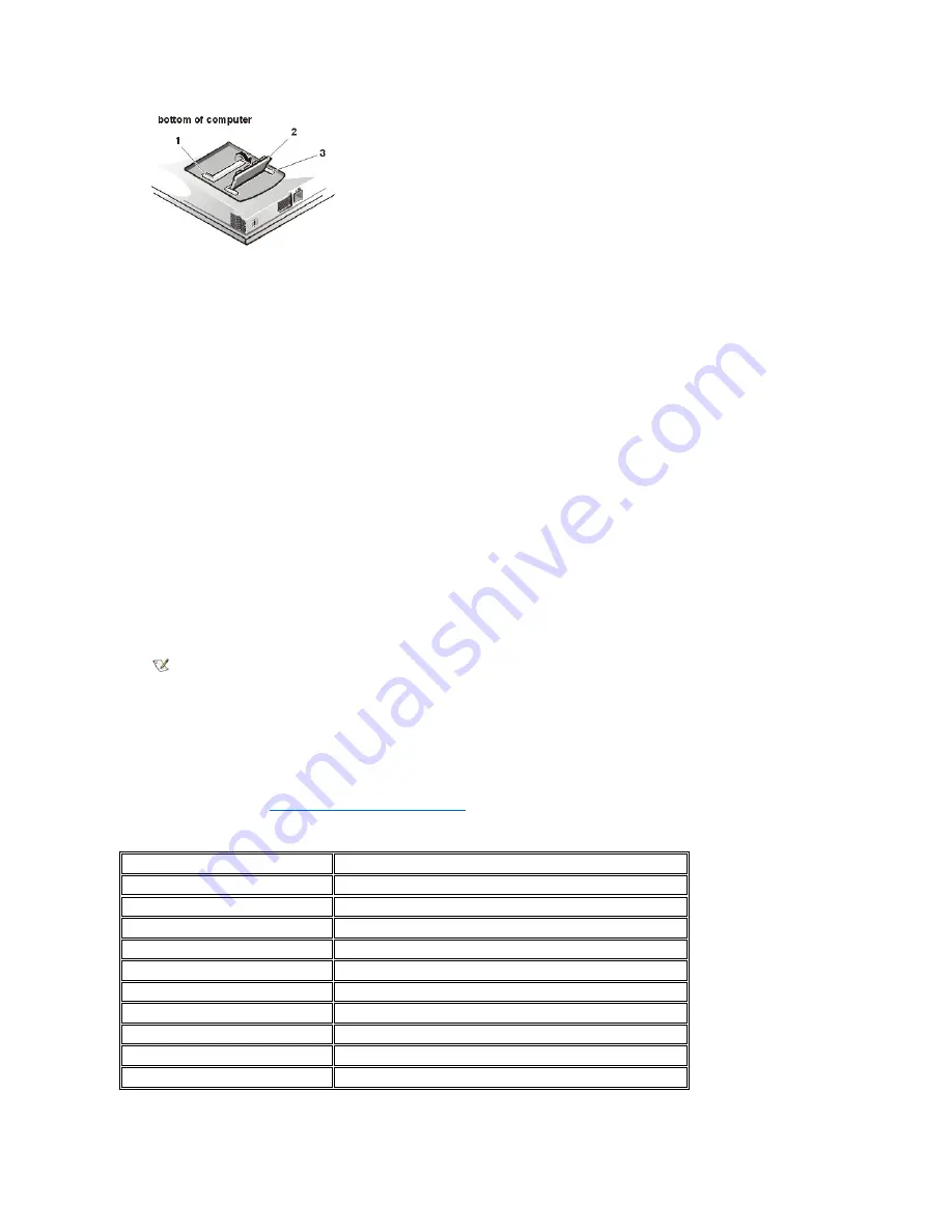
1
Slot 2
2
Memory module
3
Slot 1
NOTE: The computer will not boot without a memory module installed, nor if the installed module(s) are not seated properly in the
socket(s). No error message or beep code indicates this failure.
Location
Description
10FFF0
–
Extended memory
100000
–
10FFEF
High memory area
0F0000
–
0FFFFF
System BIOS
0E0000
–
0EFFFF
Video BIOS
0DC000
–
0DFFFF
Available
0D0000
–
0DBFFF
PC Card memory
0C0000
–
0CFFFF
Available
0A0000
–
0BFFFF
Video RAM
09FC00
–
09FFFF
PS/2 mouse-data area
000000
–
09FBFF
Conventional memory
Summary of Contents for Inspiron 7500
Page 6: ...Back to Contents Page AC Adapter Dell Inspiron 7500 ...
Page 7: ...Back to Contents Page Audio Jacks Dell Inspiron 7500 ...
Page 10: ...Back to Contents Page Component Locations Back View Dell Inspiron 7500 ...
Page 12: ...Back to Contents Page Battery Charge Gauge Dell Inspiron 7500 ...
Page 13: ...Back to Contents Page Removing and Installing a Battery Dell Inspiron 7500 ...
Page 26: ...Back to Contents Page ...
Page 38: ...Exploded View of 13 3 Inch Display Assembly Dell Inspiron 7500 ...
Page 39: ...Exploded View of 14 1 Inch Display Assembly Dell Inspiron 7500 ...
Page 44: ...Back to Contents Page Exploded View of Computer Dell Inspiron 7500 ...
Page 47: ...Back to Contents Page Component Locations Front View Dell Inspiron 7500 New artwork pending ...
Page 54: ...Back to Contents Page I O Connectors Dell Inspiron 7500 ...
Page 60: ...Back to Contents Page 30 Cone of Infrared Light Dell Inspiron 7500 ...
Page 64: ...Back to Contents Page Embedded Numeric Keypad Dell Inspiron 7500 ...
Page 89: ...Back to Contents Page PC Card Slots Dell Inspiron 7500 ...
Page 103: ...Back to Contents Page Removing the Memory Module Dell Inspiron 7500 ...
Page 104: ...Back to Contents Page Removing the Memory Module Cover Dell Inspiron 7500 ...
Page 136: ...Back to Contents Page Removing the Hard Disk Drive Dell Inspiron 7500 ...
Page 138: ...Back to Contents Page Removing Devices From the Media Bay Dell Inspiron 7500 ...
Page 140: ...Back to Contents Page Security Cable Slot Dell Inspiron 7500 ...
Page 159: ...Back to Contents Page Touch Pad Dell Inspiron 7500 ...


