


This procedure assumes that you have removed the
from the base assembly and that you have removed the
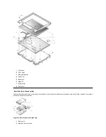
. To remove the touch pad assembly (see Figures 27 and 28), perform the following steps:
1.
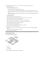
Remove the three 4-mm screws securing the touch pad button board.
2.
Disconnect the two speaker cables from connectors JP5 and JP3 on the touch pad button board.
3.
Disconnect the speaker wire harness from connector JP1 on the touch pad button board.
NOTICE: Lift away the cable only after you open the
. Pulling the cable from the connector damages the conductive
coating on the end of the cable.
4.
Disconnect the touch pad flex cable from ZIF connector JP4 on the touch pad button board.
Use the pick to pry up the latches on each side of the connector.
NOTICE: Lift away the cable only after you open the
. Pulling the cable from the connector damages the conductive
coating on the end of the cable.
5.
Disconnect the touch pad flex cable from ZIF connector J1 on the touch pad. Use the pick to pry up the brown center piece on the connector.
6.
Remove the touch pad button board.
7.
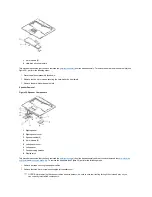
Remove the four 4-mm screws securing the touch pad bracket.
8.
Remove the touch pad bracket.
9.
Remove the touch pad.
The touch pad buttons are heat-staked into the palmrest assembly and are not removable.
Hard-Disk Drive Heat Shield Removal
Figure 29. Hard-Disk Drive Heat Shield Components
1
Touch pad bracket
2
4-mm screws (4)
3
Touch pad flex cable
4
ZIF connector
5
4-mm screws (3)
6
Touch pad button board
7
Touch pad
Summary of Contents for Inspiron 7500
Page 6: ...Back to Contents Page AC Adapter Dell Inspiron 7500 ...
Page 7: ...Back to Contents Page Audio Jacks Dell Inspiron 7500 ...
Page 10: ...Back to Contents Page Component Locations Back View Dell Inspiron 7500 ...
Page 12: ...Back to Contents Page Battery Charge Gauge Dell Inspiron 7500 ...
Page 13: ...Back to Contents Page Removing and Installing a Battery Dell Inspiron 7500 ...
Page 26: ...Back to Contents Page ...
Page 38: ...Exploded View of 13 3 Inch Display Assembly Dell Inspiron 7500 ...
Page 39: ...Exploded View of 14 1 Inch Display Assembly Dell Inspiron 7500 ...
Page 44: ...Back to Contents Page Exploded View of Computer Dell Inspiron 7500 ...
Page 47: ...Back to Contents Page Component Locations Front View Dell Inspiron 7500 New artwork pending ...
Page 54: ...Back to Contents Page I O Connectors Dell Inspiron 7500 ...
Page 60: ...Back to Contents Page 30 Cone of Infrared Light Dell Inspiron 7500 ...
Page 64: ...Back to Contents Page Embedded Numeric Keypad Dell Inspiron 7500 ...
Page 89: ...Back to Contents Page PC Card Slots Dell Inspiron 7500 ...
Page 103: ...Back to Contents Page Removing the Memory Module Dell Inspiron 7500 ...
Page 104: ...Back to Contents Page Removing the Memory Module Cover Dell Inspiron 7500 ...
Page 136: ...Back to Contents Page Removing the Hard Disk Drive Dell Inspiron 7500 ...
Page 138: ...Back to Contents Page Removing Devices From the Media Bay Dell Inspiron 7500 ...
Page 140: ...Back to Contents Page Security Cable Slot Dell Inspiron 7500 ...
Page 159: ...Back to Contents Page Touch Pad Dell Inspiron 7500 ...


