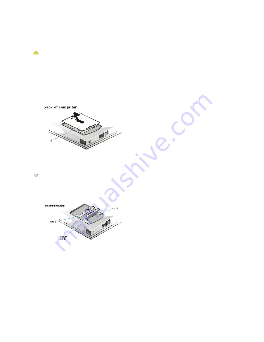
To install memory module(s), perform the following steps.
CAUTION: Before working inside your computer, read
“
Protecting Against Electrostatic Discharge
”
in the
“
Safety Instructions
”
of this guide.
NOTICE: Do not install or remove a memory module when the computer is turned on or in save-to-disk suspend mode.
1.
Save and close any open files, exit any open application programs, and shut down the computer.
2.
Unplug the computer and any attached peripherals from the electrical outlets.
3.
Remove any installed batteries from the MegaBay and/or media bay. For instructions, refer to
“
Using the MegaBay
”
and/or
“
Using the Media
Bay
”
found earlier in this chapter.
4.
Ground yourself by touching a metal input/output (I/O) connector on the back of the computer.
5.
Turn the computer over, and remove the memory module cover as shown in Figure 2-8.
Slide the memory module cover as far as it will go in the direction of the arrow, and then lift it away from the computer.
NOTICE: To prevent damage to the computer, do not use tools to spread the inner metal tabs of the socket when you are installing or
removing a memory module.
6.
If you are replacing one or more memory modules, remove the memory module(s) as shown in the figure above.
Using your fingernails, carefully spread apart the inner metal tabs of the memory module socket just far enough for the memory module
to disengage from the socket (the module should pop up slightly). Then lift the memory module away from the socket.
7.
Install the new memory module(s) as shown in the following figure:
a. Align the notch in the edge connector with the slot in the center of the memory module socket.
b. Press the memory module
’
s edge connector firmly into the socket.
c. Pivot the module down until it clicks.
from Dell (but which Dell does not install), except the 192-MB memory module, in either socket. If you purchase a non-Dell-installed 192-
MB memory module, you must install it in slot 2.
NOTE: If one memory module is already installed and you are adding a second memory module, put the second
module in the available slot. Removing existing module(s) is necessary only if they are being replaced.
Depending on the configuration of your computer, one or two modules may already be installed.
Summary of Contents for Inspiron 7500
Page 6: ...Back to Contents Page AC Adapter Dell Inspiron 7500 ...
Page 7: ...Back to Contents Page Audio Jacks Dell Inspiron 7500 ...
Page 10: ...Back to Contents Page Component Locations Back View Dell Inspiron 7500 ...
Page 12: ...Back to Contents Page Battery Charge Gauge Dell Inspiron 7500 ...
Page 13: ...Back to Contents Page Removing and Installing a Battery Dell Inspiron 7500 ...
Page 26: ...Back to Contents Page ...
Page 38: ...Exploded View of 13 3 Inch Display Assembly Dell Inspiron 7500 ...
Page 39: ...Exploded View of 14 1 Inch Display Assembly Dell Inspiron 7500 ...
Page 44: ...Back to Contents Page Exploded View of Computer Dell Inspiron 7500 ...
Page 47: ...Back to Contents Page Component Locations Front View Dell Inspiron 7500 New artwork pending ...
Page 54: ...Back to Contents Page I O Connectors Dell Inspiron 7500 ...
Page 60: ...Back to Contents Page 30 Cone of Infrared Light Dell Inspiron 7500 ...
Page 64: ...Back to Contents Page Embedded Numeric Keypad Dell Inspiron 7500 ...
Page 89: ...Back to Contents Page PC Card Slots Dell Inspiron 7500 ...
Page 103: ...Back to Contents Page Removing the Memory Module Dell Inspiron 7500 ...
Page 104: ...Back to Contents Page Removing the Memory Module Cover Dell Inspiron 7500 ...
Page 136: ...Back to Contents Page Removing the Hard Disk Drive Dell Inspiron 7500 ...
Page 138: ...Back to Contents Page Removing Devices From the Media Bay Dell Inspiron 7500 ...
Page 140: ...Back to Contents Page Security Cable Slot Dell Inspiron 7500 ...
Page 159: ...Back to Contents Page Touch Pad Dell Inspiron 7500 ...


