background image

Removing the 2280 solid-state drive from M.2 slot two

Prerequisites

1. Follow the procedure in 

Before working inside your computer

.

2. Remove the 

base cover

.

About this task

NOTE:

 If you have ordered a 3-cell (40 Wh) battery configuration, your computer will not have a solid-state drive installed

in M.2 slot two.

NOTE:

 If you have ordered a 4-cell (53 Wh) battery configuration, your computer may have a 2230 solid-state drive or a

2280 solid-state drive installed in M.2 slot two.

NOTE:

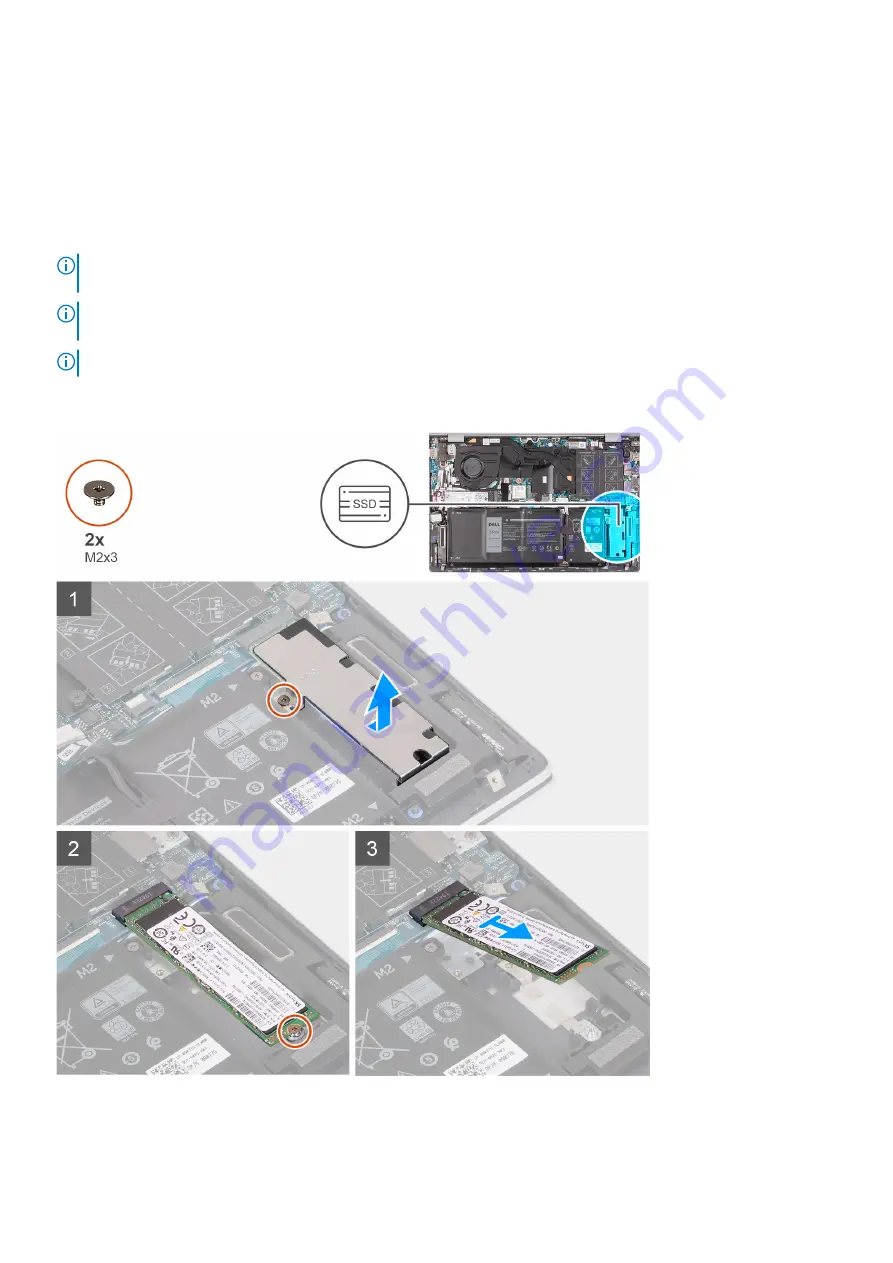
 This procedure applies only to computers shipped with a 2280 solid-state drive installed in M.2 slot two.

The following image indicates the location of the 2280 solid-state drive that is installed in M.2 slot two and provides a visual
representation of the removal procedure.

Steps

1. Remove the screw (M2x3) that secures the solid-state drive thermal shield to the palm-rest and keyboard assembly.

Removing and installing components

29

Summary of Contents for Inspiron 5405

Page 1: ...Inspiron 5405 Service Manual Regulatory Model P130G Regulatory Type P130G003 August 2021 Rev A04 ...

Page 2: ...tial damage to hardware or loss of data and tells you how to avoid the problem WARNING A WARNING indicates a potential for property damage personal injury or death 2020 2021 Dell Inc or its subsidiaries All rights reserved Dell EMC and other trademarks are trademarks of Dell Inc or its subsidiaries Other trademarks may be trademarks of their respective owners ...

Page 3: ...ot one 22 Removing the 2230 solid state drive from M 2 slot one 22 Installing the 2230 solid state drive in M 2 slot one 22 Removing the 2280 solid state drive from M 2 slot one 23 Installing the 2280 solid state drive in M 2 slot one 24 Installing the solid state drive mounting bracket on M 2 slot one 25 Solid state drive M 2 slot two 26 Removing the 2230 solid state drive from M 2 slot two 26 In...

Page 4: ...touchpad 53 I O board 55 Removing the I O board 55 Installing the I O board 55 System board 56 Removing the system board 56 Installing the system board 58 Palm rest and keyboard assembly 60 Removing the palm rest and keyboard assembly 60 Installing the palm rest and keyboard assembly 61 Chapter 3 Drivers and downloads 62 Chapter 4 System setup 63 Entering BIOS setup program 63 Navigation keys 63 S...

Page 5: ...2 System diagnostic lights 73 Recovering the operating system 73 Backup media and recovery options 74 WiFi power cycle 74 Drain residual flea power perform hard reset 74 Chapter 6 Getting help and contacting Dell 76 Contents 5 ...

Page 6: ...r computer WARNING Before working inside your computer read the safety information that is shipped with your computer For more safety best practices see the Regulatory Compliance home page at www dell com regulatory_compliance WARNING Disconnect your computer from all power sources before opening the computer cover or panels After you finish working inside the computer replace all covers panels an...

Page 7: ...failures The high rate of intermittent failures means that most of the time when damage occurs it is not immediately recognizable The DIMM receives a static shock but the tracing is merely weakened and does not immediately produce outward symptoms related to the damage The weakened trace may take weeks or months to melt and in the meantime may cause degradation of memory integrity intermittent mem...

Page 8: ...kspace should also be free of insulators that can cause an ESD event On the work area insulators such as Styrofoam and other plastics should always be moved at least 12 inches or 30 centimeters away from sensitive parts before physically handling any hardware components ESD Packaging All ESD sensitive devices must be shipped and received in static safe packaging Metal static shielded bags are pref...

Page 9: ...etic surfaces Ensure that the screws are not left attached to such surfaces when replacing a component NOTE Screw color may vary with the configuration ordered Table 1 Screw list Component Secured to Screw type Quantity Screw image Base cover Palm rest and keyboard assembly M2x4 5 Base cover Palm rest and keyboard assembly M2x7 captive 2 Battery Palm rest and keyboard assembly M2x3 3 cell 4 4 cell...

Page 10: ... Palm rest and keyboard assembly M2x2 5 2 Power adapter port Palm rest and keyboard assembly M2x3 1 USB 3 2 Type C port bracket System board M2x3 2 Display hinges Palm rest and keyboard assembly M2 5x5 4 I O board Palm rest and keyboard assembly M2x3 1 System board Palm rest and keyboard assembly M2x3 2 Major components of Inspiron 14 5405 The following image shows the major components of Inspiron...

Page 11: ...et 7 M 2 2230 solid state drive 8 speakers 9 system board 10 touchpad 11 palm rest and keyboard assembly 12 display assembly 13 power button with optional fingerprint reader 14 coin cell battery 15 I O board 16 fan 17 wireless card 18 M 2 2280 solid state drive Removing and installing components 11 ...

Page 12: ...isites 1 Follow the procedure in Before working inside your computer About this task The following images indicate the location of the base cover and provide a visual representation of the removal procedure 12 Removing and installing components ...

Page 13: ...wo captive M2x7 screws that secure the base cover to the palm rest and keyboard assembly 2 Remove the five screws M2x4 that secure the base cover to the palm rest and keyboard assembly Removing and installing components 13 ...

Page 14: ...e power button for five seconds to ground the computer and drain the flea power Installing the base cover Prerequisites If you are replacing a component remove the existing component before performing the installation procedure About this task The following image indicates the location of the battery and provides a visual representation of the installation procedure 14 Removing and installing comp...

Page 15: ...Removing and installing components 15 ...

Page 16: ...ssembly 5 Replace the five M2x4 screws that secure the base cover to the palm rest and keyboard assembly Next steps 1 Follow the procedure in After working inside your computer Battery Removing the 3 cell battery Prerequisites 1 Follow the procedure in Before working inside your computer 2 Remove the base cover About this task NOTE The following procedure applies only to computers shipped with a 3...

Page 17: ... with a 3 cell battery The following image indicates the location of the 3 cell battery and provides a visual representation of the installation procedure Steps 1 Place the 3 cell battery on the palm rest and keyboard assembly 2 Align the screw holes on the 3 cell battery with the screw holes on the palm rest and keyboard assembly 3 Replace the four screws M2x3 that secure the 3 cell battery to th...

Page 18: ...licable 2 Remove the five screws M2x3 that secure the 4 cell battery to the palm rest and keyboard assembly 3 Lift the 4 cell battery along with its cable off the palm rest and keyboard assembly Installing the 4 cell battery Prerequisites If you are replacing a component remove the existing component before performing the installation procedure About this task NOTE The following procedure applies ...

Page 19: ...he tape that secures the battery cable to the system board Next steps 1 Install the base cover 2 Follow the procedure in After working inside your computer Memory modules Removing the memory modules Prerequisites 1 Follow the procedure in Before working inside your computer 2 Remove the base cover About this task NOTE Your computer may have up to two memory modules installed The following images i...

Page 20: ... 1 to 3 to remove any other memory modules installed in your computer Installing the memory modules Prerequisites If you are replacing a component remove the existing component before performing the installation procedure About this task NOTE Your computer can support up to two memory modules The following image indicates the location of the memory module and provides a visual representation of th...

Page 21: ...ly into the slot at an angle 4 Press the memory module down until it clicks into place NOTE If you do not hear the click remove the memory module and reinstall it NOTE Repeat steps 1 to 4 if you are installing two memory modules Next steps 1 Install the base cover 2 Follow the procedure in After working inside your computer Removing and installing components 21 ...

Page 22: ...led in M 2 slot one and provides a visual representation of the removal procedure Steps 1 Remove the screw M2x3 that secures the 2230 solid state drive to the solid state drive mounting bracket 2 Slide and lift the 2230 solid state drive off M 2 slot one on the system board Installing the 2230 solid state drive in M 2 slot one Prerequisites If you are replacing a component remove the existing comp...

Page 23: ...m board 2 Slide the 2230 solid state drive into M 2 slot one on the system board 3 Replace the screw M2x3 that secures the 2230 solid state drive to the solid state drive mounting bracket Next steps 1 Install the base cover 2 Follow the procedure in After working inside your computer Removing the 2280 solid state drive from M 2 slot one Prerequisites 1 Follow the procedure in Before working inside...

Page 24: ...rocedure is applicable if you are installing a 2280 solid state drive in M 2 slot one NOTE Before installing your 2230 or 2280 solid state drive ensure that the mounting bracket is in the correct location For more information see Installing the solid state drive mounting bracket NOTE If there is only one solid state drive in the configuration you ordered you may install another solid state drive i...

Page 25: ...r Installing the solid state drive mounting bracket on M 2 slot one About this task The following image provides a visual representation of the procedure to install the solid state drive mounting bracket when replacing M 2 2230 solid state drive with M 2 2280 solid state drive in M 2 slot one NOTE If there is only one solid state drive in the configuration you ordered you may install another solid...

Page 26: ...M 2 slot two Removing the 2230 solid state drive from M 2 slot two Prerequisites NOTE If you have ordered a 3 cell 40 Wh battery configuration your computer will not have a solid state drive installed in M 2 slot two NOTE If you have ordered a 4 cell 53 Wh battery configuration your computer may have a 2230 solid state drive or a 2280 solid state drive installed in M 2 slot two NOTE This procedure...

Page 27: ...f M 2 slot two on the system board Installing the 2230 solid state drive in M 2 slot two Prerequisites If you are replacing a component remove the existing component before performing the installation procedure About this task NOTE If you have ordered a 3 cell 40 Wh battery configuration your computer will not support a solid state drive in M 2 slot two NOTE If you have ordered a 4 cell 53 Wh batt...

Page 28: ...epresentation of the installation procedure Steps 1 Align the notch on the 2230 solid state drive with the tab on M 2 slot two on the system board 2 Slide the 2230 solid state drive into M 2 slot two on the system board 3 Replace the screw M2x3 that secures the 2230 solid state drive to the palm rest and keyboard assembly 4 Place the solid state drive thermal shield on the solid state drive 5 Alig...

Page 29: ...y configuration your computer may have a 2230 solid state drive or a 2280 solid state drive installed in M 2 slot two NOTE This procedure applies only to computers shipped with a 2280 solid state drive installed in M 2 slot two The following image indicates the location of the 2280 solid state drive that is installed in M 2 slot two and provides a visual representation of the removal procedure Ste...

Page 30: ... If you have ordered a 4 cell 53 Wh battery configuration your computer may support a 2230 solid state drive or a 2280 solid state drive in M 2 slot two NOTE Before installing your 2280 solid state drive ensure that the mounting bracket is in the correct location For more information see Installing the solid state drive mounting bracket NOTE If there is only one solid state drive in the configurat...

Page 31: ...e screw hole on the solid state drive thermal shield with the screw hole on the palm rest and keyboard assembly 6 Replace the screw M2x3 that secures the solid state drive thermal shield to the palm rest and keyboard assembly Next steps 1 Install the base cover 2 Follow the procedure in After working inside your computer Installing the solid state drive mounting bracket on M 2 slot two About this ...

Page 32: ...est and keyboard assembly 3 Place the solid state drive mounting bracket into the 2280 2230 bracket slot on the palm rest and keyboard assembly 4 Replace the screw M1 6x2 5 that secures the solid state drive mounting bracket to 2230 2280 bracket slot on the palm rest and keyboard assembly 5 Install the 2230 solid state drive or 2280 solid state drive whichever applicable Wireless card Removing the...

Page 33: ... the antenna cables from the wireless card 5 Slide and remove the wireless card from the wireless card slot Installing the wireless card Prerequisites If you are replacing a component remove the existing component before performing the installation procedure About this task The following image indicates the location of the wireless card and provides a visual representation of the installation proc...

Page 34: ... wireless card slot on the system board 3 Slide and insert the wireless card into the wireless card slot on the system board 4 Place the wireless card bracket on the wireless card 5 Align the screw hole on the wireless card bracket and the screw hole on the system board 6 Replace the screw M2x3 that secures the wireless card bracket and wireless card to the system board 7 Adhere the tape that secu...

Page 35: ...l representation of the removal procedure Steps 1 Peel and lift the Mylar covering the system board 2 Lift the latch and disconnect the I O board cable from the system board 3 Remove the I O board cable from the routing guides on the fan 4 Disconnect the fan cable from the system board 5 Remove the two M2x2 screws that secure the fan to the palm rest and keyboard assembly Removing and installing c...

Page 36: ...ation procedure Steps 1 Place the fan on the palm rest and keyboard assembly 2 Align the screw holes on the fan to the screw holes on the palm rest and keyboard assembly 3 Replace the two screws that secure the fan to the palm rest and keyboard assembly 4 Route the I O board cable through the routing guides on the fan 5 Connect the fan cable to the system board 6 Connect the I O board cable to the...

Page 37: ...m s settings before removing the coin cell battery The following images indicate the location of the coin cell battery and provide a visual representation of the removal procedure Steps 1 Disconnect the coin cell battery cable from the I O board 2 Remove the coin cell battery cable from the routing guides on the palm rest and keyboard assembly 3 Peel the coin cell battery from the palm rest and ke...

Page 38: ...procedure in After working inside your computer Heat sink Removing the heat sink Prerequisites 1 Follow the procedure in Before working inside your computer 2 Remove the base cover About this task CAUTION For maximum cooling of the processor do not touch the heat transfer areas on the heat sink The oils in your skin can reduce the heat transfer capability of the thermal grease NOTE The heat sink m...

Page 39: ...orming the installation procedure About this task CAUTION Incorrect alignment of the heat sink can damage the system board and processor NOTE If either the system board or the heat sink is replaced use the thermal pad or thermal paste provided in the kit to ensure that the thermal conductivity is achieved The following image indicates the location of the heat sink and provides a visual representat...

Page 40: ...m board Next steps 1 Install the base cover 2 Follow the procedure in After working inside your computer Display assembly Removing the display assembly Prerequisites 1 Follow the procedure in Before working inside your computer 2 Remove the base cover About this task The following images indicate the location of the display assembly and provide a visual representation of the removal procedure 40 R...

Page 41: ...Removing and installing components 41 ...

Page 42: ...inges 6 Lift the palm rest and keyboard assembly off the display assembly NOTE To avoid damaging the display do not slide the palm rest and keyboard assembly over the display assembly 7 After performing the above steps you are left with the display assembly Installing the display assembly Prerequisites If you are replacing a component remove the existing component before performing the installatio...

Page 43: ...Removing and installing components 43 ...

Page 44: ...on the palm rest and keyboard assembly 6 Connect the display cable to the connector on the system board and close the latch 7 Adhere the tape that secures the display cable connector latch to the system board Next steps 1 Install the base cover 2 Follow the procedure in After working inside your computer Power adapter port Removing the power adapter port Prerequisites 1 Follow the procedure in Bef...

Page 45: ...port and provides a visual representation of the installation procedure Steps 1 Place the power adapter port into the slot on the palm rest and keyboard assembly 2 Replace the M2x3 screw that secures the power adapter port on the palm rest and keyboard assembly 3 Route the power adapter port cable through the routing guides on the palm rest and keyboard assembly 4 Connect the power adapter port ca...

Page 46: ... 2 slot two if applicable About this task NOTE The following procedure applies only to computers shipped with a 3 cell battery The following images indicate the location of the speaker and provide a visual representation of the removal procedure Steps 1 Disconnect the keyboard backlight cable and keyboard cable from the system board 2 Disconnect the speaker cable from the system board 46 Removing ...

Page 47: ...ft the speakers along with the cable off the palm rest and keyboard assembly Installing the speakers 3 cell battery configuration Prerequisites If you are replacing a component remove the existing component before performing the installation procedure About this task NOTE The following procedure applies only to computers shipped with a 3 cell battery The following image indicates the location of t...

Page 48: ...klight cable and keyboard cable to the system board Next steps 1 Install the solid state drive in M 2 slot two if applicable 2 Install the 3 cell battery 3 Install the base cover 4 Follow the procedure in After working inside your computer Removing the speakers 4 cell battery configuration Prerequisites 1 Follow the procedure in Before working inside your computer 2 Remove the base cover 3 Remove ...

Page 49: ... routing guides on the palm rest and keyboard assembly NOTE Note the position of the rubber grommets before lifting the speakers 5 Lift the speakers along with the cable off the palm rest and keyboard assembly Installing the speakers 4 cell battery configuration Prerequisites If you are replacing a component remove the existing component before performing the installation procedure About this task...

Page 50: ...eplacing the speakers 2 Route the speaker cable through the routing guides on the palm rest and keyboard assembly 3 Connect the speaker cable to the system board 4 Adhere the tapes that secure the speaker cable to the system board and palm rest and keyboard assembly 5 Connect the keyboard backlight cable and keyboard cable to the system board Next steps 1 Install the solid state drive in M 2 slot ...

Page 51: ...t the power button bracket off the power button with optional fingerprint reader 3 Remove the two screws M2x2 5 that secure the power button with optional fingerprint reader to the palm rest and keyboard assembly 4 Slide and lift the power button board from under the securing clip on the palm rest and keyboard assembly 5 Peel and lift the power button cable from the palm rest and keyboard assembly...

Page 52: ...y 5 Replace the two screws M2x2 5 that secure the power button with optional fingerprint reader to the palm rest and keyboard assembly 6 Place the power button bracket on the power button with optional fingerprint reader 7 Align the screw hole on the power button bracket to the screw hole on the palm rest and keyboard assembly 8 Replace the screw M2x2 that secures the power button bracket to the p...

Page 53: ...to the palm rest and keyboard assembly 3 Lift the touchpad bracket off the palm rest and keyboard assembly 4 Peel the tapes that secure the touchpad to the palm rest and keyboard assembly 5 Remove the two M2x2 screws that secure the touchpad to the palm rest and keyboard assembly 6 Lift the touchpad along with the touchpad cable off the palm rest and keyboard assembly Installing the touchpad Prere...

Page 54: ...assembly 3 Adhere the tapes that secure the touchpad to the palm rest and keyboard assembly 4 Place the touchpad bracket on the touchpad 5 Align the screw holes on the touchpad bracket with the screw holes on the palm rest and keyboard assembly 6 Replace the three M1 6x2 screws that secure the touchpad bracket to the palm rest and keyboard assembly 7 Connect the touchpad cable to the system board ...

Page 55: ...m the I O board 3 Disconnect the coin cell battery cable from the I O board 4 Open the latch and disconnect the power button board cable from the I O board 5 Remove the M2x3 screw that secures the I O board to the palm rest and keyboard assembly 6 Lift the I O board off the palm rest and keyboard assembly Installing the I O board Prerequisites If you are replacing a component remove the existing c...

Page 56: ...e cover 3 Follow the procedure in After working inside your computer System board Removing the system board Prerequisites 1 Follow the procedure in Before working inside your computer 2 Remove the base cover 3 Remove the 3 cell battery or the 4 cell battery whichever applicable 4 Remove the memory modules 5 Remove the 2230 solid state drive or the 2280 solid state drive from M 2 slot one 6 Remove ...

Page 57: ...display hinge to the system board 2 Pry open the right display hinge 3 Peel the tape that secures the display cable connector latch to the system board 4 Open the latch and disconnect the display cable from the system board Removing and installing components 57 ...

Page 58: ...aker cable from the system board 14 Disconnect the touchpad cable from the system board 15 Disconnect the keyboard backlight cable from the system board 16 Disconnect the keyboard cable from the system board 17 Remove the two M2x3 screws that secure the system board to the palm rest and keyboard assembly 18 Lift the system board from the palm rest and keyboard assembly Installing the system board ...

Page 59: ...he system board and close the latch 12 Adhere the tape that secures the I O board cable latch to the system board 13 Connect the fan cable to the system board 14 Adhere the Mylar that covers the system board 15 Connect the power adapter port cable to the system board 16 Adhere the tape that covers the power adapter port cable connector on the system board 17 Connect the display cable to the system...

Page 60: ...ve or the 2280 solid state drive from M 2 slot one 5 Remove the 2230 solid state drive or the 2280 solid state drive from M 2 slot two if applicable 6 Remove the wireless card 7 Remove the fan 8 Remove the coin cell battery 9 Remove the display assembly 10 Remove the power adapter port 11 Remove the speakers 3 cell battery configuration or speakers 4 cell battery configuration whichever applicable...

Page 61: ...s 3 cell battery configuration or speakers 4 cell battery configuration whichever applicable 6 Install the power adapter port 7 Install the display assembly 8 Install the coin cell battery 9 Install the fan 10 Install the wireless card 11 Install the 2230 solid state drive or the 2280 solid state drive in M 2 slot one 12 Install the 2230 solid state drive or the 2280 solid state drive in M 2 slot ...

Page 62: ...rivers and downloads When troubleshooting downloading or installing drivers it is recommended that you read the Dell Knowledge Based article Drivers and Downloads FAQ 000123347 3 62 Drivers and downloads ...

Page 63: ...ling base devices Entering BIOS setup program Steps 1 Turn on your computer 2 Press F2 immediately to enter the BIOS setup program NOTE If you wait too long and the operating system logo appears continue to wait until you see the desktop Then turn off your computer and try again Navigation keys NOTE For most of the System Setup options changes that you make are recorded but do not take effect unti...

Page 64: ...ype of hard drive installed M 2 PCIe SSD Display the M 2 PCIe SSD device information of the computer AC Adapter Type Displays the type of AC adapter System Memory Displays the size of memory installed Memory Speed Displays the speed of memory Keyboard Type Displays the type of keyboard installed on the computer Table 5 System setup options Advanced menu Advanced PowerNow Enable Enables or disables...

Page 65: ...r multimedia key as the default function key behavior Default Multimedia key Keyboard Illumination Selects the operating mode of the keyboard illumination feature Default Bright Keyboard Backlight with AC Selects the timeout value for the keyboard backlight when an AC adapter is plugged into the computer Default 1 minute Keyboard Backlight with Battery Selects the timeout value for the keyboard ba...

Page 66: ...rd is clear or set Default Not Set HDD2 Password Status Displays if the HDD password is clear or set Default Not Set Service Tag Set your system s Service Tag Admin Password Allows you to set the administrator password The administrator password controls access to the system setup utility System Password Allows you to set the system password The system password controls access to the computer at b...

Page 67: ...t menu Boot Fast Boot Enables or disables the fast boot option Default Minimal Secure Boot Enables or disables the secure boot feature Default Disabled Load Legacy Option ROMs Enables or disables the Load Legacy Option ROMs Default Disabled Boot List Option Displays the available boot options Default UEFI Attempt Legacy Boot Enables or disables legacy boot Default Disabled File Browser Add Boot Op...

Page 68: ...isplayed 2 Select System Admin Password and create a password in the Enter the new password field Use the following guidelines to assign the system password A password can have up to 32 characters The password can contain the numbers 0 through 9 Only lower case letters are valid upper case letters are not valid Only the following special characters are valid Space 3 Type the system password that y...

Page 69: ...ut this task To clear the system or BIOS passwords contact Dell technical support as described at www dell com contactdell NOTE For information on how to reset Windows or application passwords refer to the documentation accompanying Windows or your application Updating the BIOS Updating the BIOS in Windows Steps 1 Go to www dell com support 2 Click Product support In the Search support box enter t...

Page 70: ...OS FLASH UPDATE is listed as a boot option for your computer If the option is listed then the BIOS supports this BIOS update option NOTE Only computers with BIOS Flash Update option in the F12 One Time boot menu can use this function Updating from the One Time boot menu To update your BIOS from the F12 One Time boot menu you need the following USB drive formatted to the FAT32 file system key does ...

Page 71: ...will not recognize the BitLocker key You will then be prompted to enter the recovery key to progress and the system will ask for this on each reboot If the recovery key is not known this can result in data loss or an unnecessary operating system re install For more information on this subject see Dell Knowledge Base article 000134415 System setup 71 ...

Page 72: ...ferent types of BIST to check the performance of display power rail and system board These tests are important to evaluate if an LCD or system board needs a replacement 1 M BIST M BIST is the system board built in self test diagnostics tool that improves the diagnostics accuracy of system board embedded controller EC failures M BIST must be manually initiated before POST and can also run on a dead...

Page 73: ...failure 2 3 No memory or RAM Random Access Memory detected 2 4 Memory or RAM Random Access Memory failure 2 5 Invalid memory installed 2 6 System board or chipset error 2 7 Display failure 2 8 LCD power rail failure 3 1 Coin cell battery failure 3 2 PCI video card chip failure 3 3 Recovery image not found 3 4 Recovery image found but invalid 3 5 Power rail failure 3 6 System BIOS Flash incomplete ...

Page 74: ... Providers provide a modem router combo device Steps 1 Turn off your computer 2 Turn off the modem 3 Turn off the wireless router 4 Wait for 30 seconds 5 Turn on the wireless router 6 Turn on the modem 7 Turn on your computer Drain residual flea power perform hard reset About this task Flea power is the residual static electricity that remains in the computer even after it has been powered off and...

Page 75: ...NOTE For more information about performing a hard reset see the knowledge base article 000130881 at www dell com support Troubleshooting 75 ...

Page 76: ...r Express Service Code at www dell com support For more information on how to find the Service Tag for your computer see Locate the Service Tag on your computer Dell knowledge base articles for a variety of computer concerns 1 Go to www dell com support 2 On the menu bar at the top of the Support page select Support Knowledge Base 3 In the Search field on the Knowledge Base page type the keyword t...

Reviews: