Removing the speakers
WARNING:
Before working inside your computer, read the safety information
that shipped with your computer and follow the steps in
Before working inside your computer
. After working inside your computer,
follow the instructions in
After working inside your computer
. For more safety
best practices, see the Regulatory Compliance home page at
www.dell.com/regulatory_compliance
.
Topics:
•
Prerequisites
•
Procedure
Prerequisites
1
Remove the
stand
.
2 Remove the
back cover
.
3 Remove the
system-board shield
.
Procedure
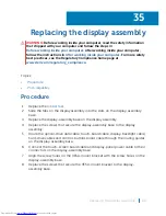
1
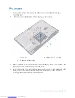
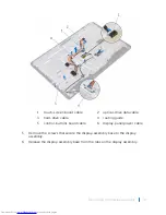
Disconnect the speaker cable from the system board.
2 Note the routing of the speaker cable and the position of the rubber
grommets on the computer bezel.
3 Remove the speaker cable from the routing guides.
4 Remove the screw that secures the tape to the display-assembly base.
5 Peel off the tape that secures the speaker cable to the display-assembly base.
6 Lift the speakers, along with the speaker cable, off the display assembly.
30
Removing the speakers
69
Summary of Contents for Inspiron 22 3000 SERIES
Page 1: ...Inspiron 22 3000 Series Service Manual Regulatory Model W17B Regulatory Type W17B001 ...
Page 25: ...1 stand riser 2 stand base Removing the stand assembly 25 ...
Page 28: ...1 back cover Removing the back cover 28 ...
Page 36: ...1 screws 3 2 hard drive bracket 3 hard drive Removing the hard drive 36 ...
Page 39: ...1 system board shield 2 screws 4 3 display assembly base Removing the system board shield 39 ...
Page 42: ...1 memory module 2 securing clips 2 3 memory module slot Removing the memory module 42 ...
Page 49: ...3 Replace the stand Replacing the wireless card 49 ...
Page 54: ...1 microphone cable 2 display assembly base 3 microphone module Removing the microphone 54 ...
Page 58: ...1 tab 2 camera cable 3 camera frame Removing the camera 58 ...
Page 61: ...1 coin cell battery 2 battery socket 3 plastic scribe Removing the coin cell battery 61 ...
Page 64: ...1 fan 2 screws 2 3 display assembly base 4 fan cable 5 system board Removing the fan 64 ...
Page 67: ...1 screw 2 heat sink 3 captive screws 5 Removing the heat sink 67 ...
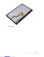
Page 81: ...1 display assembly Removing the display assembly 81 ...
Page 91: ...12 Replace the back cover 13 Replace the stand Replacing the rubber feet 91 ...


