


Cleaning the display
CAUTION:
Do not use substances such as alcohol, chemicals, or household
cleaners for cleaning the display.
CAUTION:
To avoid damaging the display, do not apply force when cleaning
and wipe off any remaining liquid after cleaning.
NOTE:
A commercial display cleaning kit should be used for cleaning. If
unavailable, use a soft, damp microfiber cloth lightly sprayed with distilled water.
1
Turn off your computer and display before cleaning.
2 Gently wipe the display in circular motion to remove any dust or dirt particles.
3 Let the display dry thoroughly before turning it on.
HDMI
The Inspiron 22–3265 supports HDMI to connect a TV or another HDMI-in enabled
device. It provides video and audio output. The HDMI port is located on the back
side of your computer.
NOTE:
Appropriate converters (sold separately) are required to connect
standard DVI and display port devices.
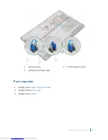
Connecting to external display devices
1
Connect the HDMI cable to your computer and the external display device.
2 Push the on/off button on the right side of your computer to switch display
modes.
Graphics
The Inspiron 22-3265 is shipped with AMD Radeon R5 A330 video controller.
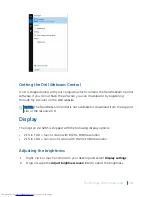
Downloading the graphics driver
1
Turn on your computer.
2 Go to
www.dell.com/support
.
Technology and components
102
Summary of Contents for Inspiron 22 3000 SERIES
Page 1: ...Inspiron 22 3000 Series Service Manual Regulatory Model W17B Regulatory Type W17B001 ...
Page 25: ...1 stand riser 2 stand base Removing the stand assembly 25 ...
Page 28: ...1 back cover Removing the back cover 28 ...
Page 36: ...1 screws 3 2 hard drive bracket 3 hard drive Removing the hard drive 36 ...
Page 39: ...1 system board shield 2 screws 4 3 display assembly base Removing the system board shield 39 ...
Page 42: ...1 memory module 2 securing clips 2 3 memory module slot Removing the memory module 42 ...
Page 49: ...3 Replace the stand Replacing the wireless card 49 ...
Page 54: ...1 microphone cable 2 display assembly base 3 microphone module Removing the microphone 54 ...
Page 58: ...1 tab 2 camera cable 3 camera frame Removing the camera 58 ...
Page 61: ...1 coin cell battery 2 battery socket 3 plastic scribe Removing the coin cell battery 61 ...
Page 64: ...1 fan 2 screws 2 3 display assembly base 4 fan cable 5 system board Removing the fan 64 ...
Page 67: ...1 screw 2 heat sink 3 captive screws 5 Removing the heat sink 67 ...
Page 81: ...1 display assembly Removing the display assembly 81 ...
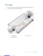
Page 91: ...12 Replace the back cover 13 Replace the stand Replacing the rubber feet 91 ...


