background image

18

  |  Removing 

the 

Optical-Drive 

Assembly

2

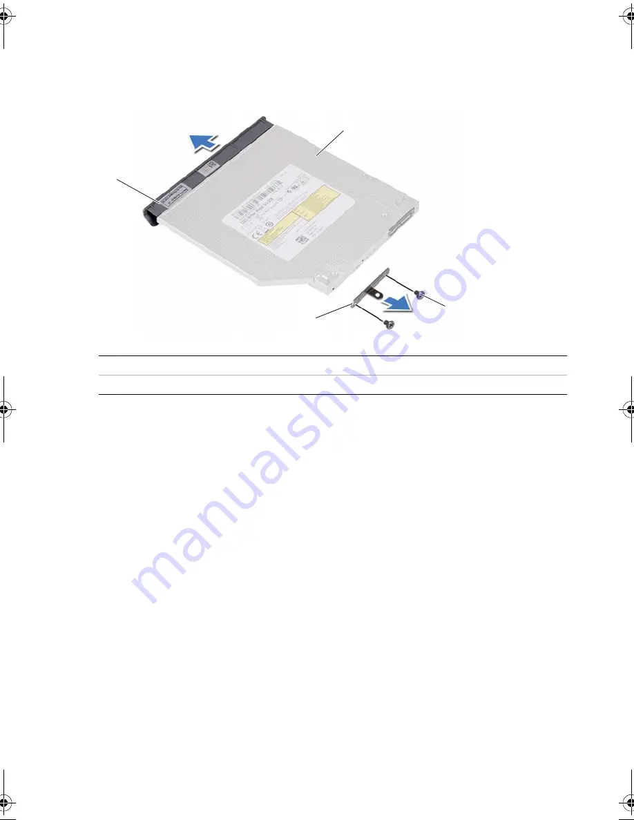
Remove the screws that secure the optical-drive bracket to 
the optical-drive assembly.

3

Remove the optical-drive bracket from the optical-drive assembly.

4

Carefully pry the optical-drive bezel and remove it from the optical drive.

1

optical-drive bezel

2

optical drive

3

screws (2)

4

optical-drive bracket

3

1

2

4

OM_Book.book  Page 18  Monday, October 15, 2012  10:01 PM

Summary of Contents for Inspiron 15z

Page 1: ...Dell Inspiron 5523 Owner s Manual Computer model Inspiron 5523 Regulatory model P26F Regulatory type P26F001 ...

Page 2: ...potential for property damage personal injury or death ____________________ 2012 Dell Inc Trademarks used in this text Dell the DELL logo and Inspiron are trademarks of Dell Inc Microsoft Windows and the Windows start button logo are either trademarks or registered trademarks of Microsoft Corporation in the United States and or other countries Bluetooth is a registered trademark owned by Bluetooth...

Page 3: ...edure 11 Removing the Memory Module s 13 Procedure 13 Replacing the Memory Module s 15 Procedure 15 Removing the Optical Drive Assembly 17 Prerequisites 17 Procedure 17 Replacing the Optical Drive Assembly 19 Procedure 19 Postrequisites 19 Removing the Keyboard 21 Prerequisites 21 Procedure 21 Replacing the Keyboard 25 Procedure 25 Postrequisites 25 Removing the Palm Rest 27 Prerequisites 27 Proce...

Page 4: ... 37 Prerequisites 37 Procedure 38 Replacing the Hard Drive Assembly 39 Procedure 39 Postrequisites 39 Removing the Wireless Mini Card 41 Prerequisites 41 Procedure 42 Replacing the Wireless Mini Card 43 Procedure 43 Postrequisites 44 Removing the Daughter Board 45 Prerequisites 45 Procedure 46 Replacing the Daughter Board 47 Procedure 47 Postrequisites 47 Removing the Speakers 49 Prerequisites 49 ...

Page 5: ...57 Procedure 58 Replacing the System Board 61 Procedure 61 Postrequisites 61 Entering the Service Tag in system setup 62 Removing the mSATA Card 63 Prerequisites 63 Procedure 64 Replacing the mSATA Card 65 Procedure 65 Postrequisites 65 Removing the Thermal Cooling Assembly 67 Prerequisites 67 Procedure 68 Replacing the Thermal Cooling Assembly 69 Procedure 69 Postrequisites 69 Removing the Displa...

Page 6: ...es 77 Removing the Display Panel 79 Prerequisites 79 Procedure 80 Replacing the Display Panel 83 Procedure 83 Postrequisites 83 Removing the Display Hinges 85 Prerequisites 85 Procedure 86 Replacing the Display Hinges 87 Procedure 87 Postrequisites 87 Removing the Camera Module 89 Prerequisites 89 Procedure 90 Replacing the Camera Module 91 Procedure 91 Postrequisites 91 Flashing the BIOS 93 ...

Page 7: ... devices from their electrical outlets 4 Disconnect all telephone cables network cables and attached devices from your computer 5 Press and hold the power button for 5 seconds after the computer is unplugged to ground the system board Safety Instructions Use the following safety guidelines to protect your computer from potential damage and ensure your personal safety WARNING Before working inside ...

Page 8: ...ity which could harm internal components CAUTION When you disconnect a cable pull on its connector or on its pull tab not on the cable itself Some cables have connectors with locking tabs or thumb screws that you must disengage before disconnecting the cable When disconnecting cables keep them evenly aligned to avoid bending any connector pins When connecting cables ensure that the connectors and ...

Page 9: ...ray screws remain inside your computer Connect any external devices cables cards and any other part s you removed before working on your computer Connect your computer and all attached devices to their electrical outlets CAUTION Before turning on your computer replace all screws and ensure that no stray screws remain inside the computer Failure to do so may damage your computer ...

Page 10: ...10 After Working Inside Your Computer ...

Page 11: ...ter Working Inside Your Computer on page 9 For additional safety best practices information see the Regulatory Compliance Homepage at dell com regulatory_compliance NOTE The SIM card slot is available in your computer only if you ordered a WWAN card at the time of purchase Procedure 1 Close the display and turn the computer over 2 Insert a small pin or unfolded paper clip into the SIM card slot pi...

Page 12: ...de your SIM card into the SIM card holder NOTE Ensure the SIM card is placed correctly in the SIM card holder 5 Push the SIM card holder back into the SIM card slot 1 SIM card slot 2 SIM card slot pin hole 3 SIM card holder 4 SIM card 1 2 3 4 ...

Page 13: ...he instructions in After Working Inside Your Computer on page 9 For additional safety best practices information see the Regulatory Compliance Homepage at dell com regulatory_compliance Procedure 1 Close the display and turn the computer over 2 Loosen the captive screw that secures the memory module cover to the computer base 3 Using your fingertips lift the memory module cover out of the slots on...

Page 14: ...tips to carefully spread apart the securing clips on each end of the memory module connector until the memory module pops up 5 Remove the memory module from the memory module connector 1 securing clips 2 2 memory module connector 3 memory module 1 3 2 ...

Page 15: ... dell com regulatory_compliance Procedure 1 Align the notch on the memory module with the tab on the memory module connector 2 Slide the memory module firmly into the connector at a 45 degree angle and press the memory module down until it clicks into place NOTE If you do not hear the click remove the memory module and reinstall it 3 Slide the tabs on the memory module cover into the slots on the ...

Page 16: ...16 Replacing the Memory Module s ...

Page 17: ...ng inside your computer follow the instructions in After Working Inside Your Computer on page 9 For additional safety best practices information see the Regulatory Compliance Homepage at dell com regulatory_compliance Prerequisites Follow the instructions from step 1 to step 3 in Removing the Memory Module s on page 13 Procedure 1 Using your fingertips slide the optical drive assembly out of the o...

Page 18: ...optical drive bracket to the optical drive assembly 3 Remove the optical drive bracket from the optical drive assembly 4 Carefully pry the optical drive bezel and remove it from the optical drive 1 optical drive bezel 2 optical drive 3 screws 2 4 optical drive bracket 3 1 2 4 ...

Page 19: ... Procedure 1 Align the tabs on the optical drive bezel with the slots on the optical drive and snap the optical drive bezel into place 2 Align the screw holes on the optical drive bracket with the screw holes on the optical drive assembly 3 Replace the screws that secure the optical drive bracket to the optical drive assembly 4 Slide the optical drive assembly into position and ensure that the scr...

Page 20: ...20 Replacing the Optical Drive Assembly ...

Page 21: ...working inside your computer follow the instructions in After Working Inside Your Computer on page 9 For additional safety best practices information see the Regulatory Compliance Homepage at dell com regulatory_compliance Prerequisites Follow the instructions from step 1 to step 3 in Removing the Memory Module s on page 13 Procedure 1 Remove the screw that secures the keyboard to the system board...

Page 22: ...ing the Keyboard 2 Turn the computer over and open the display as far as possible 3 Using a plastic scribe release the keyboard from the tabs on the palm rest assembly 1 plastic scribe 2 tabs 9 3 keyboard 1 2 3 ...

Page 23: ... Keyboard 23 4 Lift and slide the keyboard to release the tabs on the keyboard from the palm rest assembly 5 Push the battery switch to turn off the power source from the battery to the computer 1 battery switch 1 ...

Page 24: ... Lift the connector latches to disconnect the keyboard cable and the keyboard backlight cable from the system board 7 Lift the keyboard off the palm rest assembly 1 keyboard cable 2 keyboard backlight cable 3 connectors 2 1 2 3 ...

Page 25: ...cable into their connectors and press down on the connector latches to secure them 2 Push the battery switch to turn on the power source from the battery to the computer 3 Slide the tabs on the keyboard into the slots on the palm rest assembly and place the keyboard on the palm rest assembly 4 Gently press around the edges of the keyboard to secure the keyboard under the tabs on the palm rest asse...

Page 26: ...26 Replacing the Keyboard ...

Page 27: ...llow the instructions in After Working Inside Your Computer on page 9 For additional safety best practices information see the Regulatory Compliance Homepage at dell com regulatory_compliance Prerequisites 1 Follow the instructions from step 1 to step 3 in Removing the Memory Module s on page 13 2 Remove the optical drive assembly See Removing the Optical Drive Assembly on page 17 3 Remove the key...

Page 28: ...re 1 Close the display and turn the computer over 2 Gently pry out the rubber screw caps that cover the screws on the computer base 3 Remove the screws that secure the palm rest to the computer base 1 screws 8 2 rubber screw caps 7 1 2 ...

Page 29: ...5 Lift the connector latches and pull the pull tab to disconnect the status lights board cable touchpad cable touchpad status light cable and the hot key board cable from the system board 1 status lights board cable 2 touchpad status lights cable 3 touchpad cable 4 hot key board cable 4 1 2 3 ...

Page 30: ...e 7 Using a plastic scribe gently pry and release the tabs on palm rest from the slots on the computer base CAUTION Carefully separate the palm rest assembly from the display assembly to avoid damage to the display assembly 8 Lift the palm rest off the computer base 1 palm rest 2 screws 4 1 2 ...

Page 31: ...e 3 Slide the status lights board cable touchpad cable touchpad status light cable and the hot key board cable into their connectors and press down on the connector latches to secure the cables 4 Replace the screws that secure the palm rest to the computer base 5 Close the display and turn the computer over 6 Replace the screws that secure the palm rest to the computer base 7 Replace the rubber sc...

Page 32: ...32 Replacing the Palm Rest ...

Page 33: ...orking Inside Your Computer on page 9 For additional safety best practices information see the Regulatory Compliance Homepage at dell com regulatory_compliance Prerequisites 1 Follow the instructions from step 1 to step 3 in Removing the Memory Module s on page 13 2 Remove the optical drive assembly See Removing the Optical Drive Assembly on page 17 3 Remove the keyboard See Removing the Keyboard ...

Page 34: ...he Battery Procedure 1 Remove the screws that secure the battery to the computer base 2 Lift the battery to disconnect it from the system board and remove the battery from the computer base 1 battery 2 screws 5 2 1 ...

Page 35: ...egulatory_compliance Procedure 1 Align the screw holes on the battery with the screw holes on the computer base and press down on the battery connector 2 Replace the screws that secure the battery to the computer base Postrequisites 1 Replace the palm rest See Replacing the Palm Rest on page 31 2 Replace the keyboard See Replacing the Keyboard on page 25 3 Replace the optical drive assembly See Re...

Page 36: ...36 Replacing the Battery ...

Page 37: ...pliance Homepage at dell com regulatory_compliance CAUTION To avoid data loss do not remove the hard drive while the computer is in Sleep or On state CAUTION Hard drives are extremely fragile Exercise care when handling the hard drive Prerequisites 1 Follow the instructions from step 1 to step 3 in Removing the Memory Module s on page 13 2 Remove the optical drive assembly See Removing the Optical...

Page 38: ...nect it from the system board and remove the hard drive assembly from the computer base 2 Remove the screws that secure the hard drive to the hard drive bracket 3 Lift the hard drive out of the hard drive bracket 1 hard drive assembly 1 screws 4 2 hard drive 3 hard drive bracket 1 2 1 3 ...

Page 39: ... Align the screw holes on the hard drive bracket with the screw holes on the hard drive 3 Replace the screws that secure the hard drive to the hard drive bracket 4 Place the hard drive assembly on the computer base 5 Slide the hard drive assembly toward the back of the computer to connect the hard drive assembly to the connector on the system board Postrequisites 1 Replace the battery See Replacin...

Page 40: ...40 Replacing the Hard Drive Assembly ...

Page 41: ...ds from sources other than Dell If you ordered a wireless mini card with your computer the card is already installed Your computer has one half height wireless mini card slot which supports a Wireless Local Area Network WLAN Bluetooth combo card NOTE Your computer also has one full height wireless mini card slot which supports a Wireless Wide Area Network WWAN card Prerequisites 1 Follow the instr...

Page 42: ...nnectors on the wireless mini card 2 Remove the screw that secures the wireless mini card to the system board 3 Slide and remove the wireless mini card out of the system board connector 1 screw 2 antenna cables 2 3 wireless mini card 1 wireless mini card 2 system board connector 1 3 2 1 2 ...

Page 43: ...s are placed under the wireless mini card 1 Align the notch on the wireless mini card with the tab on the system board connector 2 Insert the wireless mini card connector at a 45 degree angle into the system board connector 3 Press the other end of the wireless mini card down into the slot on the system board and replace the screw that secures the wireless mini card to the system board 4 Connect t...

Page 44: ...ing the Palm Rest on page 31 3 Replace the keyboard See Replacing the Keyboard on page 25 4 Replace the optical drive assembly See Replacing the Optical Drive Assembly on page 19 5 Follow the instructions from step 3 and step 4 in Replacing the Memory Module s on page 15 6 Follow the instructions in After Working Inside Your Computer on page 9 ...

Page 45: ...puter on page 9 For additional safety best practices information see the Regulatory Compliance Homepage at dell com regulatory_compliance Prerequisites 1 Follow the instructions from step 1 to step 3 in Removing the Memory Module s on page 13 2 Remove the optical drive assembly See Removing the Optical Drive Assembly on page 17 3 Remove the keyboard See Removing the Keyboard on page 21 4 Remove th...

Page 46: ...l tab to disconnect the daughter board cable from the daughter board 2 Remove the screw that secures the daughter board to the computer base 3 Lift the daughter board off the computer base 1 daughter board cable 2 pull tab 3 daughter board 4 screw 3 4 1 2 ...

Page 47: ...ign the screw hole on the daughter board with the screw hole on the computer base 2 Replace the screw that secures the daughter board to computer base 3 Connect the daughter board cable to the daughter board Postrequisites 1 Replace the battery See Replacing the Battery on page 35 2 Replace the palm rest See Replacing the Palm Rest on page 31 3 Replace the keyboard See Replacing the Keyboard on pa...

Page 48: ...48 Replacing the Daughter Board ...

Page 49: ...on page 9 For additional safety best practices information see the Regulatory Compliance Homepage at dell com regulatory_compliance Prerequisites 1 Follow the instructions from step 1 to step 3 in Removing the Memory Module s on page 13 2 Remove the optical drive assembly See Removing the Optical Drive Assembly on page 17 3 Remove the keyboard See Removing the Keyboard on page 21 4 Remove the palm...

Page 50: ...e routing guides on the computer base 2 Disconnect the speakers cable from the system board 3 Release the speakers from the notches on the computer base 4 Lift the speakers along with the speaker cable off the computer base 1 notches 2 2 speakers cable routing 3 speakers 2 4 speakers cable 3 4 1 2 ...

Page 51: ...ce Procedure 1 Align the speakers on the computer base 2 Connect the speakers cable to the system board 3 Route the speakers cable through the routing guides on the computer base Postrequisites 1 Replace the battery See Replacing the Battery on page 35 2 Replace the palm rest See Replacing the Palm Rest on page 31 3 Replace the keyboard See Replacing the Keyboard on page 25 4 Replace the optical d...

Page 52: ...52 Replacing the Speakers ...

Page 53: ...es information see the Regulatory Compliance Homepage at dell com regulatory_compliance CAUTION Removing the coin cell battery resets the BIOS settings to default It is recommended that you note the BIOS settings before removing the coin cell battery Prerequisites 1 Follow the instructions from step 1 to step 3 in Removing the Memory Module s on page 13 2 Remove the optical drive assembly See Remo...

Page 54: ...54 Removing the Coin Cell Battery Procedure 1 Using a plastic scribe gently pry out the coin cell battery out of the battery socket on the system board 1 plastic scribe 2 coin cell battery 2 1 ...

Page 55: ... may explode if installed incorrectly Replace the battery only with the same or equivalent type Discard used batteries according to the manufacturer s instructions Procedure With the positive side facing up snap the coin cell battery into the battery socket on the system board Postrequisites 1 Replace the palm rest See Replacing the Palm Rest on page 31 2 Replace the keyboard See Replacing the Key...

Page 56: ...56 Replacing the Coin Cell Battery ...

Page 57: ... in system setup after you replace the system board NOTE Before disconnecting the cables from the system board note the location of the connectors so that you can reconnect them correctly after you replace the system board Prerequisites 1 Remove the memory module s See Removing the Memory Module s on page 13 2 Remove the optical drive assembly See Removing the Optical Drive Assembly on page 17 3 R...

Page 58: ...board 2 Remove the screw that secures the display cable to the system board 3 Disconnect the display cable from the system board 4 Disconnect the speakers cable and the daughter board cable from the system board 1 screw 2 display cable 3 speakers cable connector 4 daughter board cable 5 tape 1 2 3 4 5 ...

Page 59: ...board and release the system board ports from the slots on the computer base 7 Turn the system board over 8 Follow the instructions from step 1 to step 2 in Removing the mSATA Card on page 63 9 Follow the instructions from step 1 to step 3 in Removing the Thermal Cooling Assembly on page 67 1 screw 2 system board 1 2 ...

Page 60: ...60 Removing the System Board ...

Page 61: ... screw hole on the system board with the screw hole on the computer base 4 Replace the screw that secures the system board to the computer base 5 Connect the speakers cable and the daughter board cable to the system board 6 Connect the display cable to the system board and secure the display cable with the tape 7 Replace the screw that secures the display cable to the system board Postrequisites 1...

Page 62: ...m Board Entering the Service Tag in system setup 1 Turn on the computer 2 Press F2 during POST to enter the system setup program 3 Navigate to the Main tab and enter your computer s Service Tag in the Service Tag Input field ...

Page 63: ...liance Homepage at dell com regulatory_compliance Prerequisites 1 Follow the instructions from step 1 to step 3 in Removing the Memory Module s on page 13 2 Remove the optical drive assembly See Removing the Optical Drive Assembly on page 17 3 Remove the keyboard See Removing the Keyboard on page 21 4 Remove the palm rest See Removing the Palm Rest on page 27 5 Remove the battery See Removing the ...

Page 64: ... the mSATA Card Procedure 1 Remove the screw that secures the mSATA card to the system board 2 Slide and remove the mSATA card out of the system board connector 1 mSATA card 2 screw 3 system board connector 1 2 3 ...

Page 65: ...e angle into the system board connector 3 Press the mSATA card down and replace the screw that secures the mSATA card to the system board Postrequisites 1 Follow the instructions from step 3 and step 7 in Replacing the System Board on page 61 2 Replace the hard drive assembly See Replacing the Hard Drive Assembly on page 39 3 Replace the battery See Replacing the Battery on page 35 4 Replace the p...

Page 66: ...66 Replacing the mSATA Card ...

Page 67: ...m regulatory_compliance Prerequisites 1 Follow the instructions from step 1 to step 3 in Removing the Memory Module s on page 13 2 Remove the optical drive assembly See Removing the Optical Drive Assembly on page 17 3 Remove the keyboard See Removing the Keyboard on page 21 4 Remove the palm rest See Removing the Palm Rest on page 27 5 Remove the battery See Removing the Battery on page 33 6 Remov...

Page 68: ... from the system board 2 In sequential order indicated on the heat sink loosen the captive screws that secure the thermal cooling assembly to the system board 3 Lift the thermal cooling assembly off the system board 1 thermal cooling assembly 2 captive screws 5 3 fan cable 3 2 1 ...

Page 69: ...ial order indicated on the heat sink tighten the captive screws that secure the thermal cooling assembly to the system board 4 Connect the fan cable to the system board Postrequisites 1 Follow the instructions from step 3 and step 7 in Replacing the System Board on page 61 2 Replace the wireless mini card See Replacing the Wireless Mini Card on page 43 3 Replace the hard drive assembly See Replaci...

Page 70: ...70 Replacing the Thermal Cooling Assembly ...

Page 71: ...tory_compliance Prerequisites 1 Follow the instructions from step 1 to step 3 in Removing the Memory Module s on page 13 2 Remove the optical drive assembly See Removing the Optical Drive Assembly on page 17 3 Remove the keyboard See Removing the Keyboard on page 21 4 Remove the palm rest See Removing the Palm Rest on page 27 5 Remove the battery See Removing the Battery on page 33 6 Remove the ha...

Page 72: ...72 Removing the Display Assembly Procedure 1 Remove the screws that secure the display assembly to the computer base 2 Lift the display assembly off the computer base 1 display assembly 2 screws 4 1 2 ...

Page 73: ...ase 2 Replace the screws that secure the display assembly to the computer base Postrequisites 1 Follow the instructions from step 3 and step 7 in Replacing the System Board on page 61 2 Replace the wireless mini card See Replacing the Wireless Mini Card on page 43 3 Replace the hard drive assembly See Replacing the Hard Drive Assembly on page 39 4 Replace the battery See Replacing the Hard Drive A...

Page 74: ...74 Replacing the Display Assembly ...

Page 75: ...he instructions from step 1 to step 3 in Removing the Memory Module s on page 13 2 Remove the optical drive assembly See Removing the Optical Drive Assembly on page 17 3 Remove the keyboard See Removing the Keyboard on page 21 4 Remove the palm rest See Removing the Palm Rest on page 27 5 Remove the battery See Removing the Battery on page 33 6 Remove the hard drive assembly See Removing the Hard ...

Page 76: ...76 Removing the Display Bezel Procedure 1 Using your fingertips carefully pry up the inside edge of the display bezel 2 Remove the display bezel off the display back cover 1 display bezel 1 ...

Page 77: ...Replace the display assembly See Replacing the Display Assembly on page 73 2 Follow the instructions from step 3 and step 7 in Replacing the System Board on page 61 3 Replace the wireless mini card See Replacing the Wireless Mini Card on page 43 4 Replace the hard drive assembly See Replacing the Hard Drive Assembly on page 39 5 Replace the battery See Replacing the Battery on page 35 6 Replace th...

Page 78: ...78 Replacing the Display Bezel ...

Page 79: ... 3 in Removing the Memory Module s on page 13 2 Remove the optical drive assembly See Removing the Optical Drive Assembly on page 17 3 Remove the keyboard See Removing the Keyboard on page 21 4 Remove the palm rest See Removing the Palm Rest on page 27 5 Remove the battery See Removing the Battery on page 33 6 Remove the hard drive assembly See Removing the Hard Drive Assembly on page 37 7 Remove ...

Page 80: ...ing the Display Panel Procedure 1 Remove the screws that secure the display panel to the display back cover 2 Gently lift the display panel and turn it over 1 screws 4 2 display panel 3 display back cover 3 2 1 ...

Page 81: ...Removing the Display Panel 81 3 Peel the tape that secures the display cable to the display panel 4 Disconnect the display cable from the display panel 1 display cable 2 tape 3 display panel 2 1 3 ...

Page 82: ...82 Removing the Display Panel ...

Page 83: ...ews that secure the display panel to the display back cover Postrequisites 1 Replace the display bezel See Replacing the Display Bezel on page 77 2 Replace the display assembly See Replacing the Display Assembly on page 73 3 Follow the instructions from step 3 and step 7 in Replacing the System Board on page 61 4 Replace the wireless mini card See Replacing the Wireless Mini Card on page 43 5 Repl...

Page 84: ...84 Replacing the Display Panel ...

Page 85: ...p 3 in Removing the Memory Module s on page 13 2 Remove the optical drive assembly See Removing the Optical Drive Assembly on page 17 3 Remove the keyboard See Removing the Keyboard on page 21 4 Remove the palm rest See Removing the Palm Rest on page 27 5 Remove the battery See Removing the Battery on page 33 6 Remove the hard drive assembly See Removing the Hard Drive Assembly on page 37 7 Remove...

Page 86: ...screws that secure the display hinges to the display back cover 2 Release the display cable and the wireless antenna cables from the routing guides on the display hinges 3 Lift the display hinges off the display back cover 1 display hinges 2 2 screws 4 1 2 ...

Page 87: ...he routing guides on the display hinges Postrequisites 1 Replace the display bezel See Replacing the Display Bezel on page 77 2 Replace the display assembly See Replacing the Display Assembly on page 73 3 Follow the instructions from step 3 and step 7 in Replacing the System Board on page 61 4 Replace the wireless mini card See Replacing the Wireless Mini Card on page 43 5 Replace the hard drive a...

Page 88: ...88 Replacing the Display Hinges ...

Page 89: ... 3 in Removing the Memory Module s on page 13 2 Remove the optical drive assembly See Removing the Optical Drive Assembly on page 17 3 Remove the keyboard See Removing the Keyboard on page 21 4 Remove the palm rest See Removing the Palm Rest on page 27 5 Remove the battery See Removing the Battery on page 33 6 Remove the hard drive assembly See Removing the Hard Drive Assembly on page 37 7 Remove ...

Page 90: ...a Module Procedure 1 Peel the tape from the camera module 2 Disconnect the camera cable from the connector on the camera module 3 Lift the camera module off the display back cover 1 tape 2 camera cable 3 camera module 1 2 3 ...

Page 91: ...lace the display bezel See Replacing the Display Bezel on page 77 2 Replace the display assembly See Replacing the Display Assembly on page 73 3 Follow the instructions from step 3 and step 7 in Replacing the System Board on page 61 4 Replace the wireless mini card See Replacing the Wireless Mini Card on page 43 5 Replace the hard drive assembly See Replacing the Hard Drive Assembly on page 39 6 R...

Page 92: ...92 Replacing the Camera Module ...

Page 93: ...ot have your computer s Service Tag or Express Service Code a Select one of the following options Automatically detect my Service Tag for me Choose from My Products and Services List Choose from a list of all Dell products b Click Continue and follow the instructions on the screen 4 A list of results appears on the screen Click BIOS 5 Click Download File to download the latest BIOS file 6 In the P...

Page 94: ...94 Flashing the BIOS ...

Reviews: